Injection moulding is a production method that permits the rapid and large-scale production of components utilized in various industries. Because of how delicate this technique is and how widely it is used, there is a broad spectrum of errors that can occur throughout the Injection moulding process, and any one of these errors can cause faults in the goods that are injection moulded. Injection moulding can produce a variety of defects and industrial challenges that are quite common in the industry. But what are these defects and challenges? This article will discuss both those flaws and ways to avoid them.
The Difficulties of Injection Moulding:
Company Task Management Difficulties
1. Injection mould administration
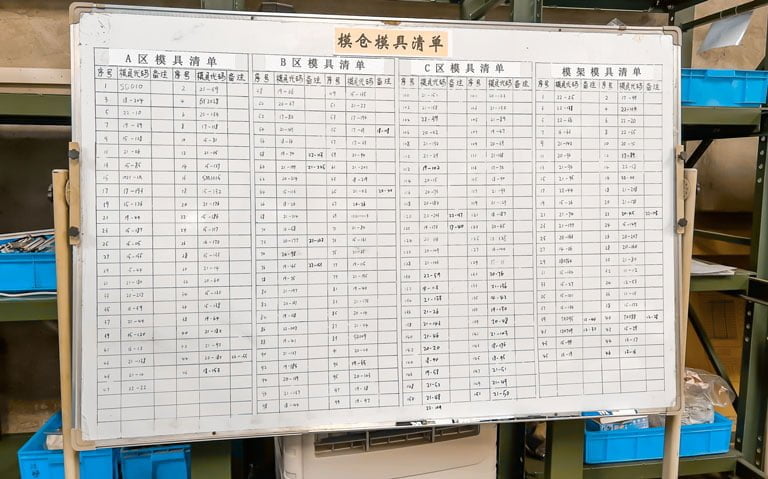
Mould management in the Injection moulding sector includes the design and development of moulds, procurement inspection, serial number management, storage issues, mould acquisition and return, mould maintenance and repair, and final disposal issues, among many other things. Moulds must be subjected to thorough data inspection and serial number management, regardless of whether purchased or created at home. When outsourcing mould, for example, involves the supplier’s delivery time, quality, and other management factors. The design and development of new moulds are also influenced by drawing management.
2. Material administration
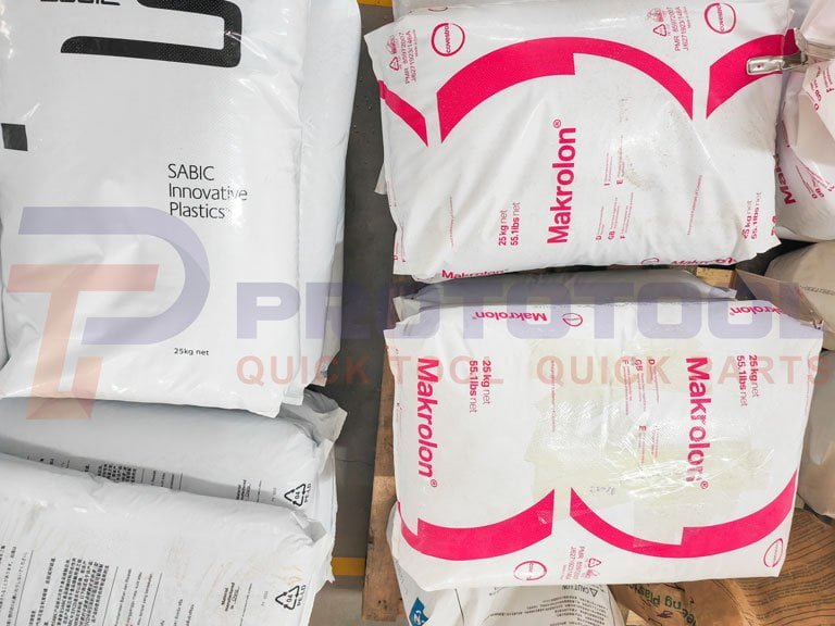
Material management includes a variety of responsibilities, such as requisitioning, returning, and reporting on items. Plastic particles and other raw materials are used in the Injection moulding industry; the quantity required for production is typically obtained through estimation; production is typically carried out following the entirety of the package. How can firms best organize their production to integrate the capacity of commodities that use the same materials to the greatest extent possible? How does one calculate the amount of raw material that goes into each work order? These questions often become concerns and difficulties, leading to further difficulties if not dealt with properly.
3. Equipment administration
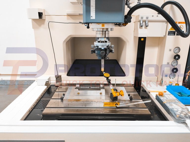
The Injection moulding industry is heavily reliant on the equipment manufacturing industry. Because general equipment is fairly expensive, the ideal condition is to keep the equipment running smoothly to maximize production efficiency and revenues. The ideal situation is to keep the equipment working smoothly. So, what should organizations do to improve their equipment’s OEE, the utilization of their assets, and the amount of downtime they experience? A simple and effective approach is TPM (total production maintenance), a lean production concept that emphasizes four “zeros.” It includes zero downtime, waste, accidents, and speed loss. Incorporating this approach during the Injection moulding workshop for manufacturing helps collect start-up time, downtime, and failure time and compute and continuously optimize overall equipment effectiveness.
Production Difficulties:
1. Temperature
a. the temperature of the oil: In the case of the hydraulic press, this refers to the heat energy created by the friction of the machine’s hydraulic oil during operation. It is controlled by the water that cools it. Before starting the machine, it is critical to ensure the oil temperature is at 45 degrees Celsius.
b. The substance’s temperature is commonly known as the barrel temperature. This temperature should be selected based on the form and function of the materials and products to be treated. If there exist files, they should be configured following the files.
c. The temperature of the mould: This temperature is also an important parameter; its level has a significant impact on the product’s performance; hence, the setting must take into account not only the function and structure of the product but also the material and the cycle.
2. Speed
The rate of movement of the opening and shutting dies: The speed at which the opening and closing dies are moved is generally determined by the slow-fast-slow principle, which takes into account the machine, the mould, and the cycle.
a. Ejection speed: This can be changed depending on the product’s structure. If the structure is intricate, slow ejection followed by fast demoulding is recommended to complete the cycle more quickly.
b. Injection speed: According to the size of the product and structure to set, if the structure is complex and the wall thickness is thin, the injection speed can be fast. Suppose the structure is simple and the wall thickness is thick. In that case, the injection speed can be slow but also, according to the performance of the material, from slow to fast.
3. Tension
Injection pressure: Determined by the size of the product and the thickness of the wall, with other factors to be considered throughout the debugging process.
a. Holding pressure: The holding pressure is generally employed to ensure that the product’s structure and size are maintained during the moulding process. The product’s structure and form should also decide the pressure at which it is set.
b. Low-pressure protection pressure: This pressure primarily protects the mould and reduces the amount of mould damage to a tolerable level.
c. Mould Clamping force: The force required by the mould to close the mould and allow it to be subjected to high pressure. Some machines can change the mould-locking force, whereas others do not.
4. Time
Glue shooting time: This time must be set longer than the actual time and can also serve as glue shooting protection. The shooting time set value should be approximately 0.2 seconds greater than the actual value, and it should be considered in conjunction with pressure, speed, and temperature.
a. Under manual situations: In this situation, the low-pressure protection time should be 2 seconds. Then, add roughly 0.02 seconds to the time based on how long it takes.
b. Cooling time: This time is frequently decided by the size and thickness of the product; nevertheless, for the product to be properly shaped after cooling, the melting time should not be longer than the cooling time.
c. Holding period: The gate is permitted to cool down before allowing the melt to flow back under the holding pressure. This is done to verify that the product will be the correct size after injection. It can be adjusted to fit various sizes, including doors and gates.
5. Positions
The opening and closing die positions: This can be modified to comply with the suitable speed of the opening and closing die. The low-pressure protection should begin at the point most likely to protect the die without interfering with the cycle. The low-pressure protection’s finishing position should be the location contacted by the front and rear dies of the die during slow closing. The key is to configure the low-pressure protection’s starting point.
a. Ejection position: In this position, the product can be demoulded. It is progressively increased from a low to a high value. Ensure that the backoff position is set to “0” during mould installation; otherwise, it is very easy to damage the mould.
b. Melt glue position: Calculate the amount of material required based on the product size and screw size, then set the position corresponding to the amount of material required.
c. The V-P position: This criterion should be determined from large to small, using the short-short approach. The V-P positions should be assigned in descending order from large to small (the V-P switching point).
Other Types of Difficulties:
· Creating a Three-Dimensional Surface of the Cavity and Core:
If the standard processing method is used, these sophisticated three-dimensional surface processing, particularly the cavity of the blind hole moulding surface processing, not only requires a high level of worker abilities but also more auxiliary fixtures, more equipment, and a longer processing cycle. Cavities and cores directly shape the external and internal shapes of plastic objects.
· Need for a Long Service Life Along with High Precision and Surface Quality:
Ordinary plastic parts must currently have dimensional accuracy of IT6-7 and surface roughness of Ra0.2-0.1m. Comparable injection moulded parts, on the other hand, must have dimensional accuracy of IT5-6 and surface roughness of Ra0.1m or below.
The roughness of the laser disk’s recording surface meets the advised mirror processing level of 0.02-0.01 micrometers. To achieve this, the surface roughness of the mould must be less than 0.01 micrometers. It is critical to have a long-lasting injection mould to boost output while decreasing costs. Currently, the usual requirement for the life of an injection mould is more than one million times.
A precision injection mould should utilize a durable mould frame, increase the thickness of the template, and increase the support column or conical positioning pieces to prevent the mould from deforming after pressure, which can sometimes surpass 100 MPa.
Because the ejector contributes significantly to the deformation and dimensional correctness of the finished product, selecting the best location for the ejector is critical to ensure that the mould releases uniformly in all areas. Because the bulk of high-precision injection moulds uses inlay or full-assembly architectures, mould part processing accuracy and interchangeability must be greatly raised to fit these designs. The operation takes a lengthy time, and the manufacturing time is limited.
The vast majority of injection moulded components are already assembled products with other parts. In many cases, they are already in other parts that have been completed and are eagerly awaiting the injection moulded parts that will support the market. After the mould has been manufactured, it must be tested and corrected regularly. As a result, development and delivery times are severely constricted. The stringent criteria for product shape or dimensional precision are combined with the various properties of resin materials.
· Off-Site Handling of Design and Manufacturing Operations:
Mould manufacturing is not the end goal, but the user proposes the final product design, and mould manufacturers design and manufacture moulds according to the user’s requirements. In most cases, the injection production of products in other manufacturers are the services provided. As a result, the product design, design and fabrication of the mould, and product manufacture all take place off-site.
· Professional Division of Labor and Synergistic Combination:
The mould production batch is small and generally belongs to the production of a single piece. Still, the mould requires many standard parts, as large as the mould frame and as small as the thimble; these cannot and will not be completed by a manufacturer alone. The manufacturing process is complex and ordinary, and CNC equipment use is extremely uneven. Mould production batches are small, and mould production is typically limited to single-piece manufacture.
Additional Moulding Manufacturing Defects and Their Solutions:
· Burns:
The surface or edge of the injection moulded object has a black or rust-colored discoloration. Burn marks, like flow lines, do not generally cause damage to the thing, but they can if the product is sufficiently damaged. Burn marks are typically caused by mould air bubbles or resin overheating during the injection. This is caused by high injection rates or material heating.
The best approach to avoid this problem is to reduce the melt, mould, and injection speeds of the moulding tool. Manufacturers can reduce burn marks by installing exhaust systems and expanding gas vents to liberate trapped air during the low-pressure injection. Finally, they may shorten the moulding cycle duration to avoid overheating trapped air or resin (injection and cooling).
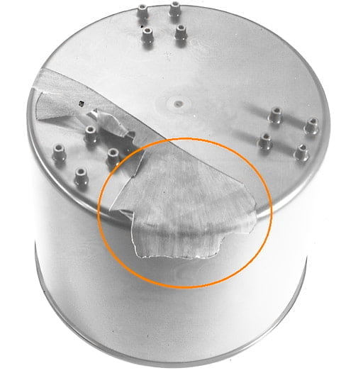
· Delamination:
When thin layers of a moulded component easily separate from the underlying material, this is referred to as surface delamination. It deteriorates components, posing a significant problem for final goods. The most common cause of delamination is foreign material contamination of resin pellets or base material. Poor binding causes flaky separation. Mould release agents, utilised to separate components, may also be impacted. Inadequate drying before usage might also result in delamination.
The cause determines delamination prevention. Resin pellets must be adequately kept and handled. Reduce the need for release agents by redesigning the mould and focusing on the injection nozzle. To remove excess moisture, raise the temperature of the mould or pre-dry the material.
· Vacuum Holes:
This frequently results in vacuum holes as a result of insufficient plastic injection. A short shot results when the moulding injection step does not inject enough plastic into the mould to make the item. When the plastic cools, it shrinks, leaving a gap in the formed product. Gas pockets can create vacuum gaps in moulded plastic. Plastic gas bubbles can form in a variety of ways, including:
- Poor venting traps air inside the mould rather than replacing it with plastic.
- As mould water evaporates, plastic resin pockets form.
- Heat causes volatile resin components to convert into gas.
- Injection moulding causes plastic material to overheat and introduces gas.
To reduce plastic resin shrinkage, troubleshooting the vacuum void entails locating the source and modifying the process by changing injection pressure, cooling rate, runner or gate size, or mould design.
· Discoloration
When moulded, things have a different hue than expected; this is called discoloration or “color streaking.” This anomaly is typically restricted to a few discolored stripes. Discoloration has an impact on appearance but not on strength.
The presence of residual resin in the nozzle, stale pellets in the hopper, or a previous manufacturing mould is frequently the source of discoloration. Poor heat conductivity of the coloring component or masterbatch mixing may also be issued.
Cleaning the machine, hopper, nozzle, and mould between manufacturing cycles removes any residual resins and chemicals, preventing discoloration. The maker should utilize a heat-conducting colour agent (in other words, it can withstand high temperatures). The masterbatch should be carefully blended for a uniform hue.
· Warping
When moulded pieces shrink unevenly, warping develops. Wood warps when it dries unevenly. The shape of the thing is twisted, uneven, or curved in unusual locations.
Premature cooling causes warping. Warpage can also be caused by heat and a lack of heat conductivity. In other cases, the mould design is blamed because shrinkage increases proportionally with wall thickness.
To avoid warping, the material should be allowed to cool gently. Determine which material to use. While cooling, particle-filled thermoplastics shrink less than semi-crystalline or empty grades. Redesign the mould to have consistent wall thickness and symmetry. This improves the stability of cooling components.
· Flash
Flash, often known as “burrs” or “spew,” is excess moulding material that protrudes from the edge of a component. Flash occurs when material pours onto the tooling plate or injector pin gap outside the specified flow paths. This malformation can be dangerous if it is visible.
Plastic seeps through the fissures when the mould is not adequately secured, resulting in a flash. It must be sufficiently sturdy to withstand the conflicting pressures of the molten plastic pouring through the mould. If the injection pressure is too high, the plastic will flow through the path with the least resistance. The main cause of this Injection moulding issue is poor mould care.
Increase the plate clamping force to prevent flashes. Other strategies include increasing material flow, mould temperature, injection pressure, and ventilation. The mould must be repaired and maintained regularly.
· Sink Marks:
These are small depressions or craters on the thicker parts of a flat part. The material pulls inward when a manufactured component shrinks.
These flaws are caused by insufficient cooling time or a cooling system that allows the plastic to cool adequately and cure in the mould. Low mould cavity pressure or high gate temperatures can also cause sink marks. Because thicker injection moulded parts take longer to cool, these issues are more common on thicker items.
Several steps must be taken to avoid sink marks. Increase the chilling time to reduce shrinkage. To accelerate cooling, reduce the thickness of the thickest wall parts. To improve cooling and curing, lower mould temperatures, raise holding pressure, and extend holding duration.
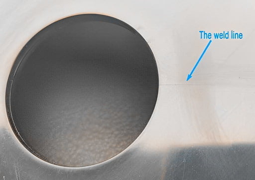
· Weld lines
Weld lines, also known as knit lines, are moulded item flaws caused by two plastic resin flows that do not join appropriately during Injection moulding. When the resin is injected into a mould, it must flow around mould impediments to form part features. The resin flow should split into two flow fronts around the barrier and recombine. When this fails, weld line flaws form.
To troubleshoot injection moulding weld lines, several factors must be investigated. Among the possible causes are:
- The injection pressure is too low, impeding resin flow.
- Lowering the process temperature causes the plastic to harden early in some mould portions.
- Uneven mould cooling is caused by slow resin flow.
- Impurities in the resin influence mould flow speed
- Overfilling the mould slows down the flow.
- Mould design issues such as gate placement and wall thickness
To optimize resin flow, increase injection pressure, add hot runners, adjust the mould to vary gate number and location, or change the resin type.
· Jetting
Jetting is a worm-track-like defect in injection-moulded products. Jetting happens when the resin is injected into the mould too quickly through a gate or runner. A snake-like stream of resin sprays into the mould cavity, cooling it before the rest of the melt can fill it. Jetting happens when a material fails to weld correctly owing to cooling.
The primary reasons for jetting are:
- The flow of mould resin shot
- Speed of resin injection
- The temperature of the resin
You can avoid mould injection into the cavity by evaluating gate placement and diameter. Other options include slowing down the ram or using hot runners or a heated mould to prevent premature plastic resin cooling. Finally, evaluate the resin and alternatives for mould temperature and cooling rate.
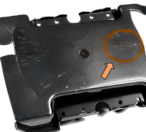
· Flowlines
Flow lines are stains, patterns, or lines that appear on the thinner areas of moulded components and are typically a slightly different color. Ring-shaped bands at mould entry locations can also appear on the surface of a product. Flow marks do not harm components, but they are undesirable for objects that must look excellent.
Flow lines are formed as the material cools through the mould. Cooling and solidification are influenced by wall thickness. Flow lines can also be produced by slow injection or low-pressure moulding.
Fill the mould before it cools. Increase the pressure, speed, and material temperature to the appropriate levels indicated. Manufacturers bend and vary wall thickness to avoid abrupt direction and flow rate changes. To slow cooling, mould gates that feed polymer solution into the final product might be positioned away from the mould coolant (used to regulate and reduce the temperature in the mould).
· Short Shots:
This happens when the plastic shot into the mould does not reach all locations. These flaws can significantly alter the appearance or function of the moulded object, making them one of the most severe Injection moulding issues. Short shots occur when the material cannot fill the mould cavities, resulting in an unfinished product after cooling.
Short shots can occur for a variety of reasons. Plastic may not fill the voids if the shot is miscalibrated. If the plastic is too dense, it may harden before filling all the holes, resulting in a short shot. Short shots are caused by insufficient degassing or gas venting, which traps air and inhibits plastic from filling the gap.
Improving mould flow is a prominent solution to this problem. This can be accomplished by redesigning the mould with broader channels and gates, increasing injection speed and pressure, or utilizing a thinner base material. Increase the temperature of the mould to slow material cooling. Build or extend air vents to assist trapped air escape. Use a less dense, more flowable plastic to fill difficult-to-reach voids.
Conclusion:
While the difficulties, issues, and faults faced by the injection moulding industry are endless, effective and professional measures can always help avoid these difficulties and ensure quality mould production.


