Managers, designers, and engineers in the manufacturing industry must understand blind holes and through holes for proper performance. This should enable them to perfect their profession.
To help you with that, this in-depth guide will unfold the strategic application of these design elements, providing valuable insights tailored to your needs as a professional or enthusiast. So keep reading to learn all about blind holes and through holes.
The Basics: Blind Holes vs. Through Holes
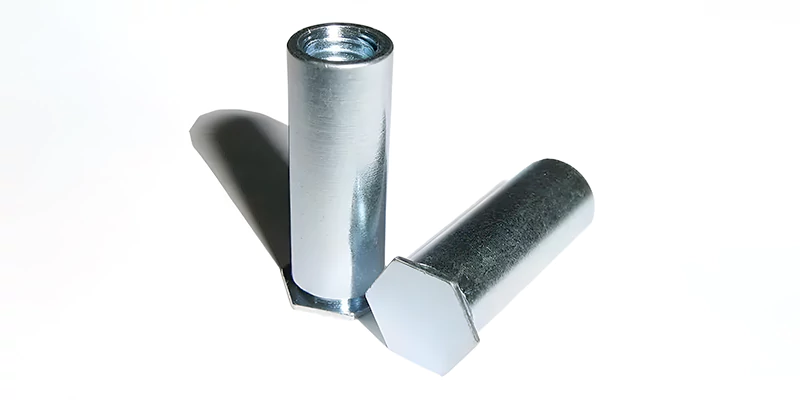
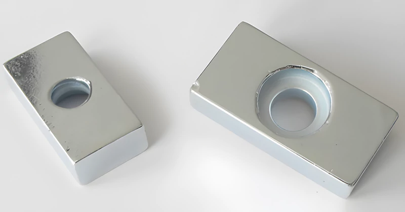
Blind holes, with a single open end, and through holes, traversing a part from end to end, are foundational in engineering. Distinguishable by symbols and manufacturing ease, the choice between them influences your design flexibility, alignment, and complexity. Let’s explore these differences further below:
- Symbol: No GD&T symbol for Blind Holes; Through Holes typically represented with a ⊗
- Manufacturing Ease: Blind Holes are generally more challenging; Through Holes are relatively straightforward
- Use Cases: Blind Holes are ideal for depth-specific scenarios; Through Holes are suitable for various applications
- Complexity: Blind Holes can have a flat bottom with effort; Through Holes have a uniform cylindrical geometry
- Customization: Blind Holes offer more design flexibility; Through Holes have standardized geometry
- Alignment: Blind Holes require precise positioning; Through Holes are easier to align during assembly
Elements and Considerations for Blind Holes
Meticulous planning is indispensable in blind hole design, encompassing depth, diameter, material properties, and part orientation. The callout ⌀.098 ↧.200, for instance, specifies a hole with a diameter of 0.098 inches and a depth of 0.200 inches. Placement and orientation significantly impact stress distribution, machining tool access, and overall aesthetics.
Tolerances, Surface Finish, and Material Considerations
- Achieving precise tolerances and suitable surface finishes is critical.
- Material properties influence decisions regarding tolerances.
- The intended application guides you toward achieving the required accuracy.
Cleaning and Drilling Techniques for Blind Holes
Efficient cleaning and drilling are crucial in blind hole manufacturing. Specialized tools, such as modified drill bits or end mills, offer customization options. Techniques like using air or high-pressure liquid coolant facilitate efficient chip extraction, contributing to the overall quality of the blind holes.
Cleaning Techniques
- Hand-operated air guns or specialized handheld hole cleaners facilitate material removal.
- Cleaning blind holes after drilling is advisable to remove leftover debris.
Drilling Techniques
- Modified drill bits or end mills are employed for creating flat-bottomed blind holes.
- Material removal of chips during drilling is crucial for preventing complications and ensuring component longevity.
Design Considerations for Blind Holes
The significance of blind holes transcends their presence in a design; it lies in the delicate balance between form and function. Planning blind holes necessitates your meticulous attention to depth and diameter, aligning with expected capability and underlying prerequisites. Material properties demand different machining settings, influencing the design of blind holes for optimal functionality.
Placement and Orientation
- Strategic placement and orientation significantly impact the usefulness and manufacturability of parts.
- Even stress distribution, easy machining tool access, and overall aesthetics become critical considerations.
- Alignment of blind holes during assembly ensures seamless integration into your larger design.
Tolerances, Surface Finish, and Material Considerations in Blind Hole Design
The achievement of precise tolerances and suitable surface finish is a nuanced process in blind hole design. Material properties, machinability, and the intended application influence decisions regarding tolerances. The intricate relationship between material properties, machining processes, and optimal surface finish guides you toward achieving the required accuracy in blind hole design.
Precision CNC Drilling with Blind Hole
Precision CNC drilling is pivotal in achieving manufacturing excellence, especially when dealing with blind holes. The drill depth clearance in blind holes is crucial to provide sufficient space for taps to effectively cut or machine the needed number of threads. The choice of tap type, material thickness, and the intended application influence the hole depth, requiring your thoughtful approach to maintain the integrity of the machining material.
Tapping Considerations in Blind Hole Design
- Blind hole design extends beyond drilling; it includes tapping considerations, where the choice of tap type and hole depth become critical factors.
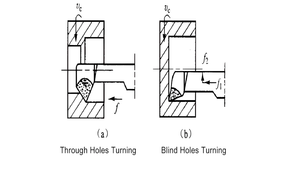
- The left-hand machine tap, with its straight flute and peel point, is suitable for through holes where chips are ejected below the hole.
- In contrast, blind holes demand a right-hand spiral flute tap where chips are removed above the hole to ensure clean cutting.
Through Hole Components
Long before the era of surface mount components, through-hole parts dominated PCB design. Despite the evolution in design preferences, through-hole components retain their significance for specific applications. Their standardized package sizes and robust mechanical attachment make them indispensable for connectors, switches, and other parts subjected to mechanical forces.
So, while surface mount components dominate contemporary PCB design, through-hole components retain their significance, especially for robust mechanical attachments. Components conducting high power or generating substantial heat find optimal solutions in through-hole connections.
Here are some key considerations for through-hole processing for designs:
Power, Durability, and Heat
- Through-hole components continue to play a vital role in PCB design, offering you unmatched durability, mechanical strength, and heat dissipation.
- Parts requiring robust mechanical attachment, such as switches, connectors, and fuses, find optimal solutions in through-hole connections.
- Through holes are favored for components conducting high power or generating substantial heat, showcasing their adaptability in your modern designs.
PCB Assembly Challenges and Solutions
- Through-hole parts present unique challenges in the PCB assembly phase.
- Manual installation or automated insertion through pick-and-place machines becomes a critical decision.
- Automated soldering through a wave soldering process demands additional considerations, such as masking surface mount components to prevent exposure to the wave.
Factors Influencing CNC Drilling Design
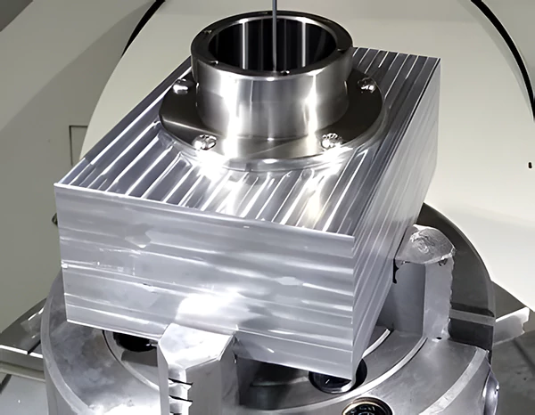
Optimizing CNC Drilling Process: Success in CNC drilling hinges on numerous factors. Exploring drill entry and exit surfaces, hole straightness, and overall part layout is crucial for achieving optimal results.
Role of Designers: You play a pivotal role in the CNC drilling process. Your responsibilities extend to optimizing drill paths, considering material characteristics, and accounting for tooling constraints. Collaboration between you and machinists is key for a seamless manufacturing process.
Design Considerations
- Drill Entry and Exit Surfaces: The significance of perpendicular entry and exit surfaces in CNC drilling cannot be overstated. Further elaborating on this aspect, you should give examples and case studies showing how it affects the outcome.
- Handling Interrupted Cuts: Challenges arise when dealing with interrupted cuts during CNC drilling. Explaining these challenges and offering strategies to minimize deflection ensures a smoother drilling process, especially in complex designs.
- Threaded Product Design: Designing products with threaded elements requires your careful consideration. Insights into incorporating chamfers and countersinks not only enhance functionality but also simplify the manufacturing process.
- Intersecting Holes: The risks associated with intersecting drilled and reamed holes are nuanced. Presenting case studies and best practices guides you in avoiding potential pitfalls and ensuring the integrity of the final product.
- Reaming Practices: Elaborating on good practices for reaming blind holes, providing guidance on extra drilled depth, and referencing a linked table for specifications enhances the precision of your CNC drilling designs.
Designing Holes for CNC Drilling
- Blind Hole Considerations: Blind holes add complexity to CNC drilling. Discussing the bottom shape of blind holes, addressing the need for standard drill points, and exploring potential alternatives provide you with valuable insights.
- Avoiding Deep Holes: Deep holes present challenges in CNC drilling, impacting tool stability and heat dissipation. Highlighting the consequences and showcasing alternative solutions, including specialized drills, guides you in making informed choices.
- Size Considerations: Choosing appropriate hole sizes is a critical aspect of CNC drilling design. Discussing the impact of small holes on production efficiency and providing practical guidelines aids you in optimizing your designs.
Coordinating CNC Drilling Design
- Coordinate Systems: Rectangular coordinates are preferred in hole location designation for CNC drilling. Emphasizing the advantages of this system, such as ease of machining, guides you in coordinating precise hole placements.
- Single-Side Drilling: Designing parts with holes drilled from a single side streamlines tooling and reduces handling time. Exploring the benefits of this approach encourages efficient and cost-effective CNC drilling.
- Standardization: Stressing the importance of standardizing hole sizes and screw threads is crucial for consistent manufacturing. Offering practical examples and industry recommendations supports you in creating designs aligned with best practices.
Calculations for Depth of Cut and Clearance
- Depth of Cut Calculation: Breaking down the calculation process for determining the depth of cut for blind and through holes provides a practical tool for optimizing your CNC drilling designs.
- Clearance Calculation: Explaining the formula for calculating clearance underscores its impact on hole quality, accuracy, and tool performance. This knowledge empowers you to fine-tune your designs for optimal results.
Still have questions? Contact our professional team at Prototool to assist you with understanding the entire blind or through hole drilling process.


One Response
Can you be more specific about the content of your article? After reading it, I still have some doubts. Hope you can help me.