Resource optimization and higher efficiency are integral parts of the molding industry. And a hot runner works as the most suitable tool to achieve both. Businesses use them to eliminate scarp plastic, providing faster cycle time and increasing. You can also achieve high quality by transferring the melt to the mold. Their hot tip and valve gate configuration ensure that the system gets a customizable approach to building its processor solution. As a result, the molding system provides higher efficiency.
However, the design of a hot runner plays a crucial role in determining its complete potential utilization. Therefore, understanding the designing process and structure of a hot runner is a fundamental factor for industry experts. If you are new to the designing process of hot runners, you have landed in the right place. We will discuss different components involved in the design and the process of designing the hot runner.
Different aspects of designing
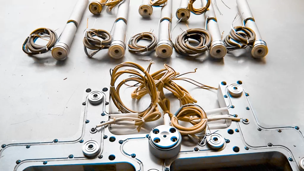
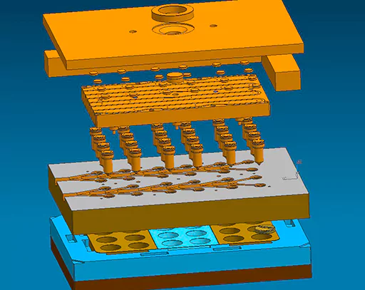
A hot runner comprises a manifold plate, backing plate, cooling plate, etc. These components work in integrated processes to provide the final efficiency. So to design a hot runner, experts take segmented approaches for different components. Ultimately, these component designs are incorporated to get the final machine. Therefore, we will also discuss the separate components with a view to ultimate incorporation to get the complete hot runner at the end of the design process. Let’s begin.
Manifold plate design
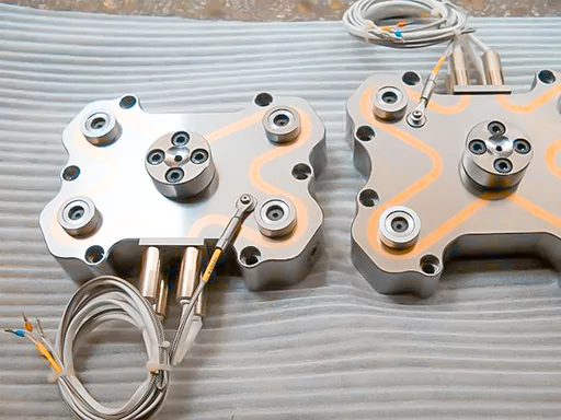
The manifold plate of the hot runner has three primary operations to perform. The first one is to provide support to other components. The second is to offer a surface area for backing plate bolts. At last, the manifold plate also works as backup support for the cavity plate. For creating an efficient hot runner design, the manifold plate must fulfill these three functions without fail.
The following essential factor to consider in the manifold plate design is alignment. The alignment of the manifold plate allows the smooth travel of molten plastic from the machine nozzle to the gate. In addition, there are fixed melt channels throughout the manifold plate to transport molten plastic. If the plate is not aligned correctly, then there can be several issues in molding. For instance, poor color change can occur, and in severe cases, the complete hot runner can leak, damaging the whole machine.
Therefore, the design should accommodate suitable locations for insulators, bolts, and nozzles. The design of the manifold plate should also come with tight tolerances to provide smooth functioning.
Meanwhile, The design should have a solid attachment of manifold and backing plate to provide complete support for the components. The design can have types of attachments. At first, only one plate is used to back the manifold and nozzle parts. Then, a contoured pocket is made in the second, similar to a manifold, into one plate.
The following structure is the pillar which should accommodate enough space for the manifold. The primary function of pillars is to provide resistance against the deflection of the plate in regions with high pressure. The pillars can be designed on the surface or the inside regions of the manifold plates. During the designing process, if the engineers make integral pillars, their radius should be taken on the base. This will decrease the saturation of stress at one point.
In most hot runner designs, the manifold plate is also responsible for providing cavity plate support. So the manifold plate design should also be in alignment with the cavity plate parts. In addition, leader pins and wire channels should have a viable distance between them.
The next crucial factor in overseeing the designing process is the condensation process of the manifold plate. So to avoid any trapped water, proper channels are required in the manifold plate. This will avoid corrosion due to condensed water by draining it properly outside the hot runner.
Backing plate Design
The next crucial component of the design is the backing plate. We read how the manifold plate provides support to the backing plate. This reflects in the design of the manifold plate. However, now we will discuss the design of the backing plate as per its functions.
The backing plate’s primary function is to support the hot half of the mold. In addition, it helps in stationary platen of the molten plastic. It features clamp slots along with mounting bolt locations. Moreover, the hot runner backing plate may have air or hydraulic lines.
The functionality range of the backing plate is determined by its attachment to the manifold plate. This makes the attachment design essential; otherwise, the efficiency of the hot runner can be affected. Therefore, the hot runners come with plate bolts for the backing plate. It prevents the issue of plate separation because of increased thermal expansion. Therefore, if the hot runner has 2 to 8 drops, then it should have at least 3 bolts in its design.
The position of these bolts should be at each drop to form a triangle structure. This design will help in reducing the distortion due to uneven waste. However, when we talk about extensive-scale systems, then space becomes an issue. In such cases, the design should include a shared bolt pattern. Finally, the backing plate should be torque by the center point of the plate for a smooth assembly design. This will manage the torque distribution, resulting in efficient structure maintenance of the plate.
Even pressure distribution in the design to avoid Plate deflection
If any plate deflection arises, the pressure inside the hot runner will be distributed unevenly. This will change the location of the core, and the resultant molding will not be appropriate. Therefore, the hot runner plate design includes a single plate with a manifold pocket. This further outlines the manifold and the pillars; as a result, the plate deflection decreased by around 86%.
Design and development for plate cooling
The plate temperature requires regular maintenance. So the hot runner needs to have cooling lines for stabilization. If it has an efficient cooling system, it avoids heat transfer to the mold. Otherwise, the heat can cause decreased sealing force. Further, the thermal expansion inside the hot runner structure will lead to misalignment. Moreover, the heat produced by the hot runner can also increase the temperature of the machine’s stationary plate.
Therefore, the ideal scenario of the hot runner design comprises a cooling circuit near the plates adjoined to heated components. The cooling circuit should also dissipate the heat to ensure uniform temperature throughout the hot runner. Therefore, the design needs a substantial heat and temperature management system to keep the hot runner efficient.
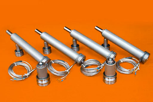
Plate material
The plate material also plays a crucial role in the hot runner design. As per the availability of the resources, the design of the hot runner is determined. The space and the scale of the production also play a significant role in deciding the plate material. Usually, the hot runner is composed of stainless steel or P20. Stainless steel is preferred because of its corrosion resistance. It is because the water and vapor are nearby of the hot runner. So this makes it vulnerable to corrosion which is avoided by using a non-corrosive material.
Tips for a perfect hot runner design
We have now understood the different components and operations involved in the hot runner design. We discussed the factors affecting the components and our resultant design prototype. Now, we will discuss a few tips that can further enhance a well-structured hot runner’s design.
- Several years of development have resolved the dead spot issue in the hot runners. Otherwise, the material of these spots is used to degrade over time. Therefore, using a reliable material with a uniform protective coating in the hot runner is the best way to ensure that no degradation occurs on the metal surface of the body anywhere.
- The tip designs are the next issue causing a hot runner segment. This impacts the cycle time and gate vestige, resulting in hang-ups. Therefore, three hot drop tip designs are developed to resolve concerning issues. Each tip design comes with variations that can produce the required effect of resolution for the overall performance of the tip.
For instance, a low vestige tip provides minimum vestige and decreases the stringers. However, sometimes this design can also create fill pressures which lead to discoloration of the molding process in different colors. This will also resolve the plugging issues because of the low volume of the orifice.
The next tip design is straight through, creating no noticeable coloring or contamination issues. There are several new designs in development that can lead to insulating gaps. However, a straight-tip design can reduce the percentage of such issues in the final molding process.
There is another tip design which is called a valve gates structure. It also offers minimal vestige while providing better control over the flow. In addition, it provides easy shutting down of the valve gates whenever required.
Conclusion
Hot runner plates are crucial for ensuring the smooth performance of the mold. They are responsible for molding as well as its efficiency. Therefore, the design of the hot runners becomes essential to get desired results at the end of the molding process. However, a poorly designed plate can lead to core issues and misalignment. This will damage the internal slides and the vents leading to a high cost of repair and molding damage. Therefore, the design of the hot runner plate should consider the different aspects of performance, such as plate deflection and cooling.


