Due to its precision, several issues may arise throughout the injection molding process. The cosmetic or structural integrity of the part can be compromised by anything from operator error to flaws in the mold design. One common error manufacturers often face during this process is flow lines defect in injection molding.
Now if you’re a professional manufacturer who often faces flow line issues during the production process, it’s time you learn how to solve or prevent this issue from affecting the quality and outlook of the produced parts. This article will take you through all the ins and outs of flow lines defect in injection molding.
Also Read: What Causes Ejected Mark In Injection Molded Parts & How Can You Solve It?
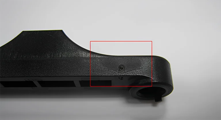
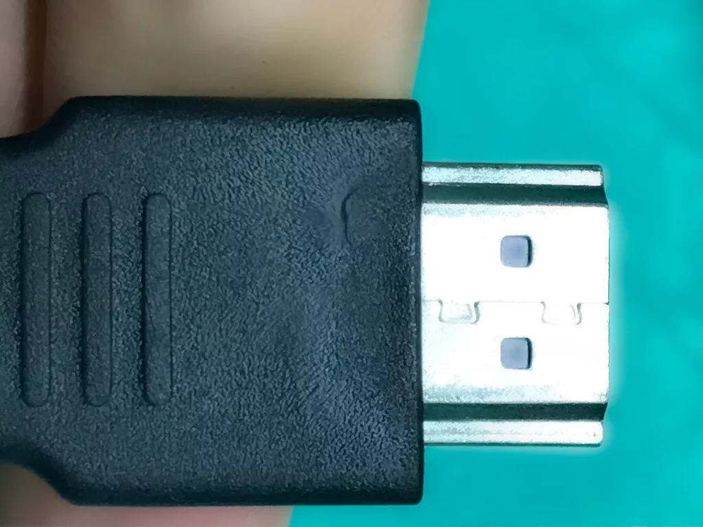
Recognizing Flow Lines:
On the surface of a plastic object, flow lines most frequently take the form of a wavy pattern. However, flow lines can also take on a variety of other patterns. They almost always have a distinguishable hue from the remainder of the component and are more likely to be seen where the item is particularly narrow.
Injection molding flow lines typically fall into one of the categories mentioned in the following table:
| Category | Type of Flow Line | Appearance (What It Looks Like) |
| 1. | Snake Lines | The appearance of snake lines is caused by the formation of a jet effect as the melt travels through a gate and into the mold cavity. The resulting line has the appearance of a snake and can be found on the surface of the product. |
| 2. | Wave Lines | Wave lines are typically caused by melt-flowing speeds that are inconsistent. The melting process either speeds up or slows down, which results in the melting process meandering and producing wavy lines. |
| 3. | Radiation Lines | When the molten material sprays as it enters the cavity through a gate, the pattern it leaves behind on the part’s surface is radial. In most cases, this will produce a radial line. |
| 4. | Fluorescent Lines | The product will take on a lustrous appearance as a direct result of the stress and pressure caused by the flow of the melt. Because this flaw looks something like a firefly, it is also called a glowing line. |
What Causes The Flow Lines Defect in Injection Molding?
Four primary categories classify the causes of flow lines. Each of these categories has a variety of problems that can affect the production of the product and lead to defects. Let’s begin by exploring the different procedures of the injection molding process. We’ll also look into the specific errors that can occur during these procedures, leading to flow lines.
Injection Molding Process Errors:
Errors in the injection molding process can result in various problems, especially flow line defects. Some specific errors that can lead to flow lines on the product during the injection molding process include:
- Insufficient holding or injection pressure results in inadequate pressing of the solidified melt on the mold surface. Thus, flow line defects aligning with the melt flow direction can occur in the injection-molded product.
- If the cycle duration is too short, the melt might not be heated adequately while it is contained within the barrel. When the temperature at which the material melts is low, it is impossible to compact the material while it is being held under pressure, which results in flow lines. This problem is frequently associated with insufficient residence time, which also results in the melt being retained in the barrel for insufficient time.
- The low temperature in the barrel is also worth considering because it can result in a low temperature in the melt. These temperatures affect the holding and injection pressure by assuring that it will not be high enough to keep layers of solidified melt against the surface of the mold.
- Lastly, inside the barrel, the nozzle is the location of the ultimate heating zone. It transfers heat to the molten substance. If the nozzle is not heated adequately, the melt temperature will drop, resulting in the pressure difficulties discussed earlier.
Errors in the Mold:
Undeniably, the mold design is an essential part of the injection molding process. Some specific problematic scenarios when using the mold can lead to the occurrence of flow lines in the final product. These issues/scenarios include:
- Increasing the size of a runner, gate, or sprue above what is necessary results in increased flow resistance. This issue, when coupled with low injection pressure, results in a decrease in melt speeds and has the potential to generate flow lines.
- When the melt is injected into a mold that has a lower temperature, the material temperature declines at a faster rate. When molten material at a higher temperature is poured on top of material that has been solidified at a lower temperature, the temperature gradient causes flow lines to form.
- If the mold is not evacuated properly, there is a risk of blockages occurring. The melt front cannot force the solid material layer against the mold, which results in the formation of flow lines.
Flow Lines Due To Defects In The Material:
Injection molding flow lines can also be caused by using material that has defects. If a mold cavity has a significant flow length-to-thickness ratio, the material should have a low enough viscosity to enable a continuous flow.
This can be accomplished by reducing the substance’s viscosity. If it does not, the lack of fluidity of the material creates a slow flow of melt, generating the previously described concerns with cooling and pressure.
In this scenario, the formation of flow lines can result from a failure to raise the material’s lubricant content in accordance with the flow length-to-wall thickness ratio. The higher this ratio gets, the higher the minimum amount of lubricant content must be used.
Also Read: 11 Widely Used Products Made by Injection Molding Today
Errors Made While Operating an Injection Molding Machine:
Operator mistakes can also cause flow lines to appear in part. For instance, if the operator of the injection molding machine mistimes the process of flipping the door, this results in erratic heat loss, which the machine then has to try to adjust for.
Because the temperature is not evenly distributed, cold patches emerge in the mold, leading to flow line formation.
Countermeasures for Flow Lines Defect in Injection Molding:
Snake Lines:
Solution#1:
Adjust the mold gate size based on the cavity depth relative to the gate depth.
As a result, the jet expansion mixes the melt behind the gate with the front edge, masking its effect.
This happens when the gate depth is slightly less than the cavity depth. When gate depth equals cavity depth or is close, mold filling rate is low, causing spreading flow.
Solution#2:
Make the necessary adjustments to the angle of the mold gate. The angle between the mold gate and the moving mold is 45 degrees.
This indicates that when the melt flows out of the gate, it will be stopped first by the mold cavity wall, preventing snake movement. The angle between the mold gate and the moving mold is 45 degrees.
Solution#3:
Move the mold doors to a more convenient position. Because the mold gate is placed perpendicular to the mold cavity wall (perpendicular to the gate’s direction), the mold cavity wall first stops the melt out of the gate.
This prevents the emergence of jet flow and causes it to become an extended flow, eliminating the appearance of a snake flow line. When the gate is placed perpendicular to the mold cavity wall, it is also perpendicular to the gate’s direction.
Wave Lines:
Solution#1:
Bring the temperature of the mold up to the desired level. As the mold temperature rises, the melting fluidity will continue to increase.
When it comes to crystalline polymers, a higher temperature encourages crystallization homogeneity, which minimizes waviness’s visibility.
Solution#2:
Alter the way in which the cavity is configured. The mold structure may also be responsible for the appearance of wavy lines on the product’s surface. A high resistance to melt flow is observed when the mold core’s edges and corners are pronounced.
This leads to melt flow instability, resulting in the development of wavy lines. Adjusting the edges and corners of the mold core can help eliminate the appearance of wavy lines by producing a buffer transition and maintaining a continuous flow of molten plastic.
Solution#3:
Modify the product so that it has the desired thickness. The variable thickness of the component results in a fluctuating resistance to the flow of the molten material, which in turn leads to an unstable flow of the molten material.
Because of this, the injection-molded product will have a consistent thickness throughout, which will also help to prevent the appearance of wavy lines.
Radiation Lines:
Solution#1:
Adjust the profile of the door molds as necessary. By increasing the gate size or transforming it into a fan-shaped gate, it is possible to gradually recover the flexibility of the melt until it reaches the cavity of the mold.
Because of this, melt fracture can be avoided.
Solution#2:
Elongate the primary runner of the mold as much as possible. It is feasible to stop the melt from extending past the mold cavity until it reaches its final destination. Switch out the equipment for one that has a nozzle that is significantly longer.
To increase the melt’s elastic failure, lengthen the flow route into the mold cavity. This will prevent radiation lines from forming as a result of melt fracture.
Fluorescent Lines:
Solution#1:
Bring the temperature of the mold up to the desired level. When compared to the temperature of the mold, there is a reduction in fluorescent lines on the surface of products, an acceleration in the relaxation of macromolecules, a reduction in molecular orientation and internal tension, and a reduction in molecular orientation.
Solution#2:
Altering the structure of the cavity could result in an increase in the product’s thickness.
Why is that? As the product thickness increases, several effects follow: the cooling of the melt becomes slower, the stress relaxation time extends, the orientation stress decreases, and there is a decrease in fluorescence lines.
Solution#3:
The utilization of heat, such as in a baking oven or a pot of boiling water.
In this scenario, applying heat stimulates macromolecular activity, decreases relaxation time, and heightens depolarization’s effect, ultimately reducing the number of fluorescence lines.
Also Read: Why Should You Consider CNC Prototyping? Usage Needs, Limitations, and Expert Tips
Produce and Launch Defect-Free Injection Molded Products With The Assistance of Prototool’s Professional Manufacturers:
In plastic injection molding, avoiding the formation of flow lines is essential for producing a high-quality finished product.
By addressing the common causes of flow line defects in injection molding and collaborating with a manufacturer or supplier experienced in resolving such issues, you can ensure that the final outcome will possess both appealing aesthetics and structural durability.
This is where Prototool assists you in making your products defect-free. From the prototype stage through production, Prototool takes a preventative approach to ensure no faults appear in the final product.
So if you’re looking for a reliable collaborator to help ensure your next production project is error-free and the products are ready to hit the market right after the production, we are always there to help you make it possible!
Contact us at Prototool today!


