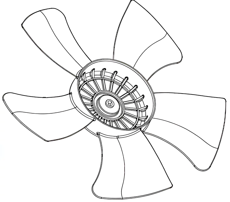
When a fan rotates, its angled blades continuously push the air from behind forward, creating wind through air shearing. The centrifugal force generated by the rotating fan blades directs the airflow. The maximum wind force and speed occur when the blades are at a 45-degree angle to the centerline, with the most dispersed wind at 90 degrees. From a mechanical perspective, fan blades are typically odd-numbered, with 3 or 5 blades being common. This asymmetry helps in energy efficiency. When one blade is at a low energy potential, the others, being at a higher potential, can easily drive it using inertial forces.
Design Specifications of the Fan Blade
A well-known brand’s fan blade product measures ø335.50 mm x 42.30 mm. It has an average wall thickness of 3.20mm, is made of PP material, and has a shrinkage rate of 1.008. The design incorporates a stainless steel insert at the center of the plastic part to enhance wear resistance. The technical requirements stipulate no defects like peaks, insufficient injection, flow lines, pores, warping, silver streaks, cold material, jetting, or bubbles. The use of mold release agents is prohibited during the molding process.
Principles of Fan Blade Mold Design
The fan blade part, as shown in Figure 1, has a relatively simple design. This article discusses the design and manufacturing highlights of fan blade molds. It focuses on two primary requirements: the principle of center of gravity alignment and dynamic balance. Poor-quality fans often suffer from “eccentricity” due to manufacturing defects, leading to noise, vibration, and increased wear over time. Ensuring balance in mold design and improving manufacturing processes are crucial for high-quality fan blade production.
Mold Layout and Gating System
The part is nearly circular, with 5 blades evenly distributed along the perimeter. Given its size, the mold cavity layout is 1×1, with the mold base being FAI 4545 A60 B60 C135. The fan blade shape necessitates a point gate injection system. The large size of the part requires 5-point gates. Each is located near the edge of the central dome, close to each blade, as illustrated in Figure 2. A balanced gating system ensures even distribution of material, crucial for the dimensional and weight uniformity of each blade.
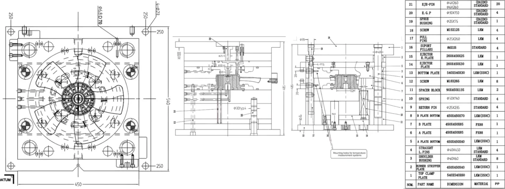
Mold Structure and Cooling System
The mold structure is straightforward, lacking complex sliders or inclined mechanisms. All design and machining aspects revolve around “balance.” The design of the mold’s cooling system achieves equilibrium. It is sandwiched between front plates 5 and 6 and rear plates 7 and 8. The system features large circular cooling channels and sealing rings. Strategically, we place thermocouples on the A plate and B plate to monitor and control temperature.
Machining and Assembly for Precision
Balancing is not only crucial in mold design but also in machining. The front and back mold cores require high-speed machining with high-quality tools and new blades to ensure identical shape and dimensional tolerances for each blade. After precision machining, a 3-coordinate inspection is mandatory before assembly.
Rapid mold clamping is essential in modern injection molding for efficient production. This mold uses a mechanical rapid clamping system with V-grooves designed on the fixed and moving mold plates, with tight tolerances on width, angle, and plate thickness.
The connection between the 5 blades and the central dome is a tilted joint, requiring the front and back mold cores to interlock. A small draft angle of 0.25º on the outer side of the dome’s sidewall meets aesthetic requirements without hindering demolding, considering the PP material.


