The temperature control system of an injection mold directly impacts the quality of the molded product and the efficiency of production. High temperatures on the mold cavity surface can lead to flash at the parting line and sink marks in thicker sections of the plastic part. Conversely, low temperatures can cause poor filling and weak weld lines. Uneven temperatures across the mold cavity and moving mold surfaces can introduce internal stresses, leading to warping and deformation in the molding process. Thus, the temperature control system, akin to the gating system, is crucial in mold design and warrants significant attention.
Design Principles for Injection Mold Cooling Systems
To enhance the efficiency of the cooling system and ensure uniform temperature distribution across the mold cavity, the following principles should be adhered to:
1. Optimal Cooling Method and Circuit Placement:
During mold design, prioritize the cooling method and circuit placement, ensuring sufficient space for turbulent water flow in the cooling channels. The cooling circuit should meet the molding process requirements, providing ample, uniform, and balanced cooling.
2. Temperature Differential and Flow Dynamics:
Consider the temperature differential at the inlet and outlet and calculate the flow pressure drop to determine the appropriate diameter and length of the cooling channels. Aim for a lower temperature differential (5°C for standard molds, 2°C for precision molds). The length of the cooling circuit should be between 1.2 to 1.5 meters, with a flow speed of 0-1.0 m/s, and the number of bends should not exceed 15. For larger molds, consider multiple independent circuits to increase coolant flow and reduce pressure loss, enhancing heat transfer efficiency. Multiple narrow cooling channels are preferable to a single large diameter channel.
3. Number and Size of Cooling Channels:
Maximize the number and size of cooling channels, with the diameter depending on the shape of the plastic part and the mold structure. The number, spacing, and proximity of the channels to the molding space significantly impact mold temperature control.
4. Strategic Cooling Near the Gate:
The area near the gate, often in contact with the injection molding machine’s nozzle, tends to have higher temperatures and requires intensified cooling. If necessary, design a separate cooling channel for this area.
5. Avoid Cooling at Weld Lines:
Since weld lines are the coolest areas, avoid placing cooling channels near them to prevent exacerbating weld line defects and reducing the strength of the plastic part at these points.
6. Placement of Water Inlet and Outlet Connections:
Position these connections on the non-operational side of the mold.
7. Separate Cooling Circuits for Movable and Fixed Molds:
Ensure balanced cooling for both the cavity and the core, with special attention to the cooling efficiency of the core to guarantee uniform cooling and shrinkage of the plastic part.
Key Considerations in Cooling System Design
1. Cooling Methods for Different Molds:
Use rapid cooling for standard molds to shorten the molding cycle and gradual cooling for precision molds, incorporating mold thermometers.
2. Minimize Use of Sealing Rings:
Design cooling circuits with dual straight-through paths for easier maintenance. Ensure leak-proof seals and check for water leakage at the seals and nozzles.
3. Directional Cooling for Specific Materials:
For materials like PE with significant shrinkage, orient the cooling channels along the shrinkage direction to prevent deformation. Align the channels with the layout of the mold cavity.
4. Cooling Circuit Configuration:
For molds with a single inlet and outlet, use a series connection for the cooling channels. For parallel connections, ensure each circuit has a flow control device and flow meter to maintain uniform cooling conditions.
5. Enhancing Cooling in Challenging Areas:
In areas where cooling is less effective or structurally limited, consider using materials with high thermal conductivity, like beryllium copper or copper alloys, or a heat-conducting rod structure. Provide cooling for cores, inserts, and sliders as necessary.
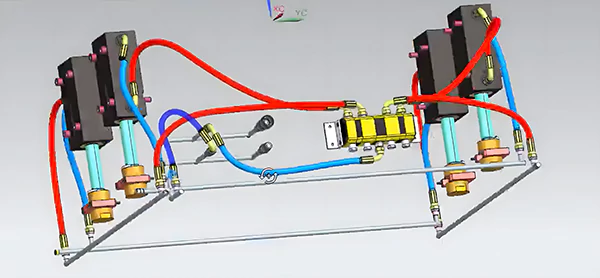
6. Color-Coding and Labeling:
Mark the water inlet with red and the outlet with blue. Label the cooling water inlets and outlets on the movable and fixed mold plates with “IN” and “OUT” in English, and group the water channels accordingly.


