The remote control mold design not only dictates its functionality but also it is aesthetic appeal and user experience in consumer electronics. Prototool’s journey in creating a plastic remote control mold design combines innovation with precision. This offers a glimpse into the meticulous process of bringing a simple yet essential gadget to life.
Client’s Remote Control Product Requirements
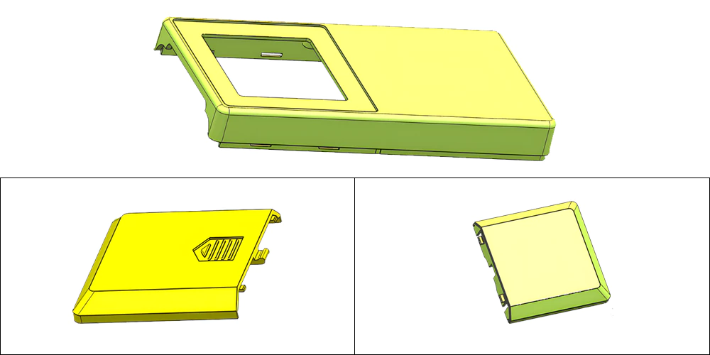
The remote control casing typically comprises a top shell and a bottom shell, as illustrated in Figure 1. The top shell’s maximum dimensions are 100.00 mm x 50.00 mm x 10.00 mm, with an average wall thickness of 1.50 mm. Made from ABS material, the top shell has a shrinkage rate of 1.005 and weighs 10.55 grams. It is imperative that the plastic parts are free from defects such as weld lines, short shots, flow marks, air pockets, warping, silver streaks, cold slugs, and jetting, and they must comply with ROSH environmental standards.
Structure Analysis And Mold Design Of The Remote Control Product
The remote control’s top and bottom shells consist of three plastic parts. The top shell is a single piece, while the bottom shell includes a battery cover. The overall design of these parts is a flat frame structure, connected along the perimeter through snap-fits. These snap-fits require the design of angled lifters or lateral sliders for core pulling mechanisms.
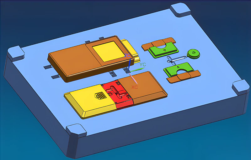
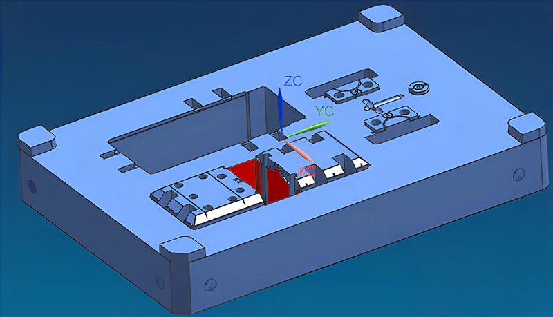
As shown in Figure 3, the mold layout adopts a family mold design. This design includes the top shell, bottom shell, battery cover, and three internal small components. Family molds are advantageous in prototype stages or small-scale production due to their cost-effectiveness. However, they present challenges in high-precision products because achieving balanced runner systems is difficult. This complication makes the injection molding process more complex. For series production, flow switch components can be designed to adjust production quantities based on demand.
Mold Assembly and Precision
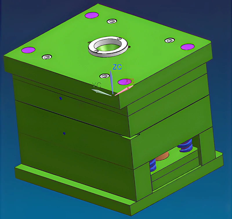
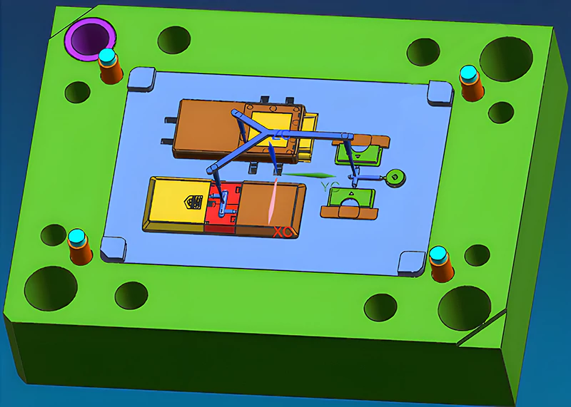
Figure 3 shows the arrangement of the six plastic parts to achieve a balanced runner system. The mold design utilizes a simplified FCI3040 A60 B90 standard mold base with S136 for the cavity and NAK80 for the core. We position the cavity and core using a four-corner inter-lock method. This must align with the mold core structure to save steel and reduce machining time. Sometimes, the direction of the inter-lock considers cavity strength. In this case, the cavity side is recessed and the core side protrudes to tighten and prevent cavity expansion under injection pressure. The inter-lock’s side angle, typically between 5° to 10°, significantly impacts mold closing precision. The smaller the angle, the higher the precision.
Side Snap-Fits and Ejection Mechanism
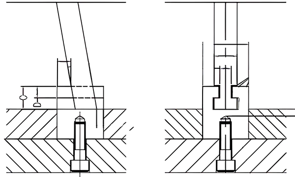
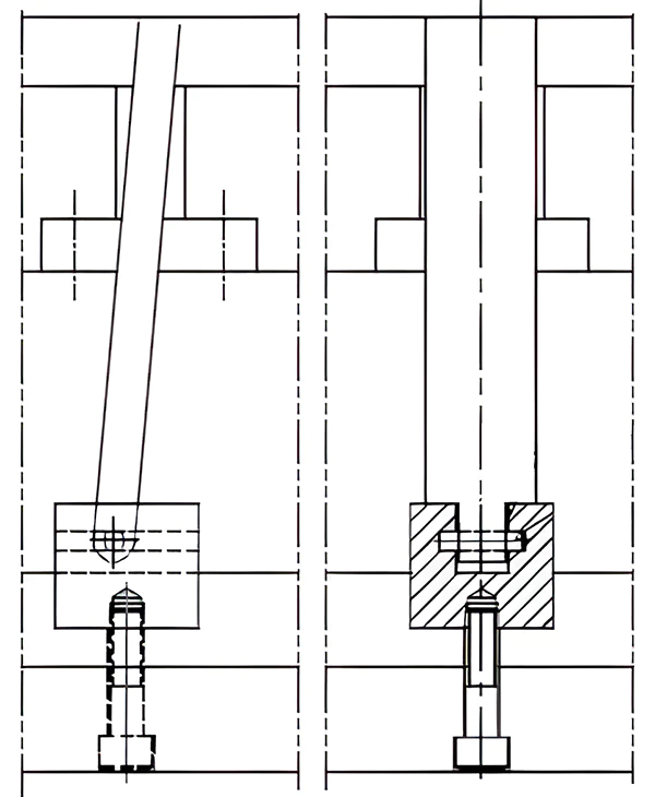
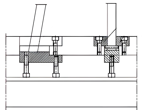
The side snap-fits of the top and bottom shells are resolved using angled lifters for ejection. There are various angled lifter structures, commonly using T-slot or roller drives. Due to the small size of the plastic parts and limited space, the guide block for the small angled lifter is designed on the back of Plate B. Figures 6 and 7 illustrate the T-type angled lifter seat and the pin structure angled lifter seat, respectively. The pin diameter should be at least ø4mm, and the slider seat hardness above HRC40.
Innovations in Angled Lifter Design
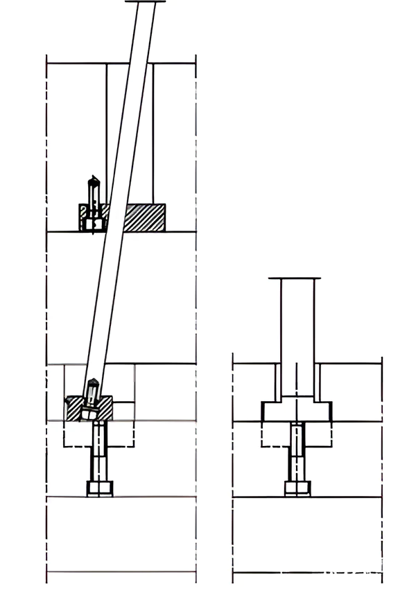
Figure 8 displays a screw-connected angled lifter seat structure. In this structure, the lifter seat is screwed to the bottom of the angled lifter, with a spring washer underneath to prevent loosening. Adding wear blocks to the push plate facilitates maintenance and replacement after wear. Figure 9 presents an improved version of the pin structure angled lifter seat. The pin diameter is at least ø4mm, and the flat bottom surface of the angled lifter bears the injection pressure, significantly improving the force condition compared to the design in Figure 7.
Conclusion
In designing plastic remote control molds, attention to detail in every component—from the mold layout to the ejection mechanism—is crucial for producing high-quality, defect-free plastic parts. By adhering to these design principles and leveraging innovative techniques, manufacturers can ensure efficient production and meet stringent environmental and quality standards.


