Injection molding is a common and adaptable manufacturing technology that allows businesses to generate high-volume production runs at a cheap cost per part without losing quality. It is extremely reproducible and capable of creating strong components that fulfill precise mechanical and dimensional specifications. Thin wall injection molding can be used when a company has to make a plastic part with thin walls, such as certain automotive parts or cell phone cases. Yet, you must exercise extreme caution when developing goods with thin walls, as thin wall injection molding presents additional obstacles.
In this article, we’ll go over the fundamentals of thin-wall injection molding, its common applications, and some injection molding design advice to help you ensure that your thin-wall injection molding-required corporate plastic goods are made to perfection.
A Brief Overview of Thin Wall Injection Molding
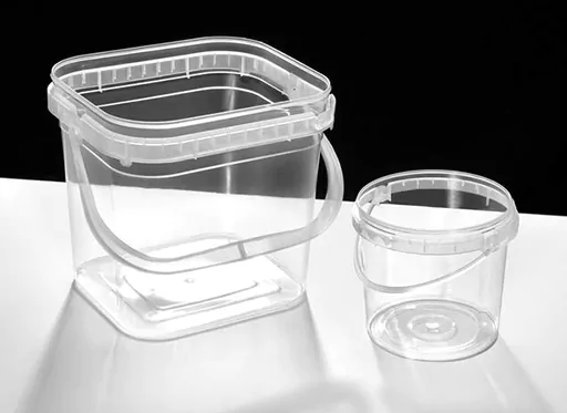
Thin wall injection molding is a subset of conventional injection molding that focuses on mass-producing thin and light plastic parts to save money on materials and keep cycle times as short as feasible. Shorter cycle durations imply increased production and cheaper per-part costs.
The definition of a thin wall refers to the part’s size concerning its thickness. Making any plastic object using the injection molding technique is harder as the wall thickness decreases. The size of a part limits the amount of wall thickness that can be used. For packaging containers, a thin wall means less than 0.025 inches (0.62mm) wall thickness with a flow length to wall thickness ratio larger than 200.
This injection molding technique includes shorter delivery lead times and faster cycle times due to less material to cool down. In fact, a large reduction in wall thickness can sometimes cut cycle times in half, allowing businesses to get products into customers’ hands faster while saving money on operational costs.

Now thinner walls also imply less plastic, which means your organization can save money on materials and provide more vacant space for the product in containers and packaging. However, there are a few drawbacks to thin wall injection molding. For one thing, the injection process is more difficult. More pressure and faster molding speeds are required to fill the thin cavities with molten material, avoid freezing off, and ensure the item comes out correctly.
The Benefits of Thin Wall Injection Molding
While there are multiple benefits that come along with the choice of thin wall injection molding manufacturing approach, some key benefits of this process include:
- Low-cost, safe, and sanitary plastic components.
- Thin wall molding saves resources and decreases weight, lowering fuel use and carbon emissions in transport and aiding sustainability efforts.
- In automobile applications, lighter parts lower fuel emissions.
Thin Wall Injection Molding: Important Considerations
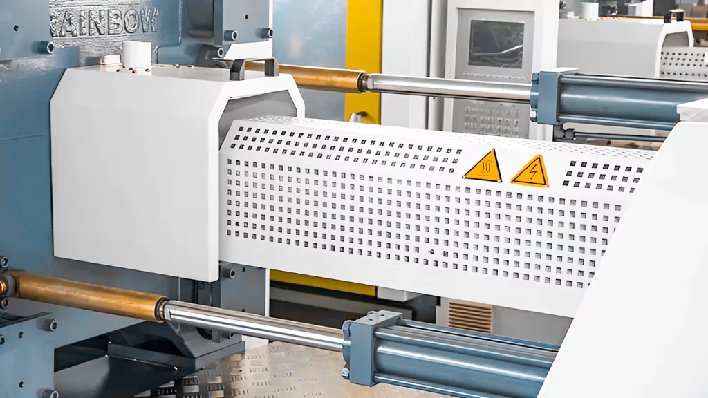
Considering the Ideal Machinery:
Modern standard molding machinery has advanced capabilities that surpass those of a decade ago, making them suitable for a wide range of thin-wall applications. The capabilities integrated into modern standard machines far exceed those of ten years ago. Materials, gating technology, and design improvements further extend a typical machine’s ability to fill thinner parts.
However, as wall thicknesses decrease, a more specialized press with higher speed and pressure capabilities may be necessary. It is not unusual for a portable electronic component less than 1 mm thick to have fill times of less than 0.5 seconds and injection pressures exceeding 30,000 psi. Accumulators are often used in thin-wall molding hydraulic machines to drive both the injection and clamping cycles. Models that are all-electric or hybrid electric/hydraulic with high speed and pressure capabilities are also becoming available.
In addition, in this process, clamp force should be at least 5-7 tons/square inch of predicted area to withstand the high pressures required. Also, extra-heavy platens reduce flexure when wall thicknesses decrease, and injection pressures rise. Thin-wall machines typically have a tiebar distance to platen thickness ratio of 2:1 or less. Closed-loop control of injection speed, transfer pressure, and other process variables can also help manage to fill and pack with thinner walls at high speeds and pressures.
Furthermore, large barrels tend to be too large regarding shot capacity. We recommend aiming for a shot size of 40% to 70% of the barrel capacity. The considerably reduced total cycle time found in thin-wall applications may allow for a 20%-30% reduction in minimum shot size, but only if the parts are properly evaluated for property loss owing to probable material deterioration.
Having said that, machine operators must exercise caution since small shot sizes can result in longer barrel residence durations for the substance, causing property degradation.
Selecting the Best Materials:
When deciding which material to use for your part, remember that the proper material depends on the geometry of your part and the needs of your application.
Some materials, such as thermoplastics such as:
- high-density polyethylene (HDPE)
- low-density polyethylene (LDPE)
- polypropylene (PP)
- nylon, flow smoothly through thin areas (PA)
Now, these are all ideal product choices for parts with a live hinge, a thin section that must bend. Another thermoset substance is liquid silicone rubber (LSR), which fills extremely easily—so much so that it can provide a flash risk on separation lines. By including additional characteristics in the mold design, we can help prevent flash.
Polycarbonates, conversely, are sticky and have difficulties filling geometries with thin walls. Portion wall thickness should be taken into account while deciding on a material.
Design Suggestions:
Here’s a list of tips to bear in mind while developing and selecting a material for molded parts with walls:
- In general, maintaining a uniform wall thickness of 0.060 to 0.120 in. (1.5-3.0mm) throughout your design will guarantee that the pieces cool evenly and prevent warping.
- Consider adding gussets (cross-support ribs) to provide a more durable thin rib wall without making the rib thicker.
- Ribs should be approximately 50-60% of the thickness of the main foundation, as indicated in the photo to the right. Ribs with the same thickness throughout can leave additional material at the rib’s base.
- While parting lines (the seam where two halves of the mold join) are to be expected on most molded items, changing the location of your parting line can make a significant visual difference. Your quote will specify the placement of the parting line, and we may suggest altering the shape to a less prominent location.
- Furthermore, incorporating flow channels with radii to thin geometry can help material flow more freely into thin ribs or sections.
Above all, early submission of your CAD file allows us to provide input on your design and guide you through the injection molding manufacturing process. If we anticipate any problems with wall thickness or component geometry in general, we can advise you on how to solve them as soon as possible so that you receive your finished parts on time.
Additional Design Tips:
Apart from the basics, you can suggest the thin wall injection molding manufacturing and design professionals you are here to consider the following tips during the process:
- For aggressive thin-wall applications, utilize steel stronger than P20, especially if considerable wear and erosion are predicted. H-13 and D-2 steels have proven to be effective in gate inserts.
- Mold interlocks can occasionally prevent flexing and misalignment.
- Telescoped cores can aid in reducing core displacement and breakage.
- Under the cavities and sprue, use stronger support plates (commonly 2 to 3 thick) with support pillars (usually preloaded 0.005 in.).
- To reduce pin pushing, use more and larger ejector pins than with standard molds.
- Focus on strategically arranging sleeve and blade knockouts.
- No. 2 diamond polish on cores and ribs can eliminate part sticking issues. Mold surface treatments such as nickel-PTFE can also improve a part release.
- Venting is crucial and can be aided by vented core pins, ejector pins, and venting along up to 30% of the separating line. Vents are approximately 0.200 to 0.0400 wide and 0.0008 to 0.0012 deep. While it is not normally essential, some processors have used an O-ring to seal the separating line to pull a vacuum on the cavity for rapid gas evacuation.
- When injection speeds increase, gates with larger than nominal walls help reduce material shear and gate wear while also preventing freeze-off before proper packing is attained.
- Gate inserts with a Rockwell (Rc) hardness of more than 55 are commonly employed to sustain high injection pressures.
- Use gate wells to reduce tension at the gate, aid filling, and reduce part damage while delegating when gating directly onto a thin wall with a sprue, pinpoint, or hot drop.
- Hot manifolds can assist in reducing pressure loss in runner systems, but they require inner channels with at least 0.5-in. diameter and no sharp corners or dead zones. External, rather than interior, heaters should be used in manifolds. If valve gates are utilized, they must be non-restrictive and engineered to withstand high pressure.
Summing Up
Thin wall plastic components are in high demand worldwide due to their durability, faster cycle times, and lower source material requirements. In thin wall molding process, plastics can meet the majority of customer demands. Thin wall plastic molding is one of the classic injection molding technologies used to create low in weight, sturdy and reliable, and cost-effective plastics.
With thin wall injection molding becoming more popular in every industry, it’s time you consider it for your products’ manufacturing needs too.


