If you’ve ever handled an injection molded component when manufacturing plastic products, you know that they typically have a defining line around their outer periphery. But why do you need to mold this line? How is it formed? And does it affect the quality of the plastic product or not? These can be certain concerns that you should look into in the parting line.
If you are unfamiliar with the parting line, this article will help you explore it in detail. So without further ado, let’s dive into the details.
Parting Line Injection Molding – Definition
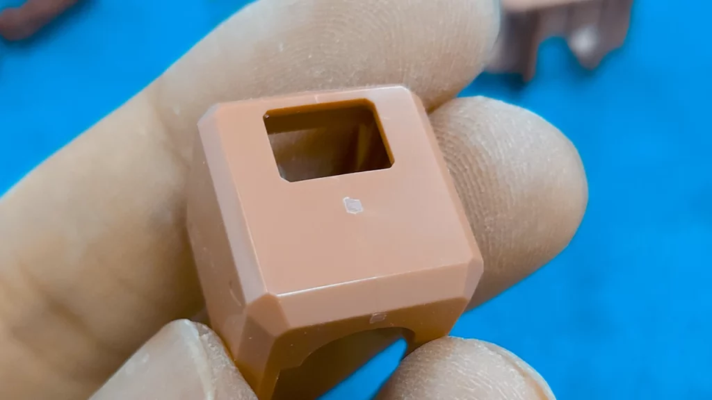
A parting line in plastic injection molding is where two closed halves of a mold meet. Now, the injection mold divides a plastic product into two sections, and the line that separates the products is known as the parting line. Plastic is poured into the mold at high pressure, solidifying with surface characteristics or faults. Hence, in the instance of the separating line, it will show as a slightly elevated line on the part’s surface.
Now when it comes to the parting line, it is nearly impossible to avoid or eliminate the parting line. However, you can mitigate the effect by practicing methods like camouflaging the line by incorporating it with other parallel or linear design features.
- Disguise the lines with rough surface textures and matte finishes
- Put sand on the lines smoothly and repaint afterward
- Set the parting line under a protruding feature such as a rim or cap
Secondary techniques to eliminate parting line flash include vibratory tumbling, hand trimming, media blasting, and cryogenic de-flashing
Parting Line Formation:
Once you understand what a parting line in injection molding is, it’s time to explore how to form this line during the plastic injection molding process. Now a parting line is a separating line that separates the core and cavity portions of a molded item or a borderline where draft angles change direction. It can be used to produce the parting surface of the mold as well.
Parting lines are formed due to the injection molding process rather than an error. Molds used by machinists to produce injection molded products are typically separated into two pieces (known as the fixed half and the moving half). When the machinists close the mold body, a parting line is formed between the mold halves (the core plates) and the surface of the cavity.
Now a molded object’s separation line is usually perpendicular to the opening direction of the mold used to produce the product. The movable half of the mold moves and separates from the fixed half when the machinist opens the mold and removes the cooled and solidified item (which is stationary). This explains the entire process of forming the dividing line.
Nonetheless, as a machinist or manufacturer, you will sometimes have to part the mold structure numerous times from different directions. This is referred to as multi-step separating.
Determining the Parting Line:
When establishing the parting line, we must first define the shape and position of the parting line on the plastic molded item. Only then can we move on to determining the parting line itself. After selecting the direction in which the mold hole will be cut, it is much simpler to locate the separating line. The parting line projection aligned with the plastic component projection in the direction of mold opening.
Thus a straight line that is perpendicular to the direction of the mold opening can be slid along the projection’s outer contour. The point at which the straight line reaches the surface can be calculated for each coordinate. This is possible because the plastic portion’s projection along the parting line in the direction of the mold opening is identical to the parting line’s projection.
The parting line for a two-color mold is also determined by the design and aesthetic needs of the final product during injection molding. It is also considered if the processing can be done and where the mold layout’s follow-up glue will be placed. The following are the three classifications that can be applied to it:
- If the straight line crosses the object surface in a straight line segment, any point along the straight line segment where the straight line meets the object surface can be used as a point on the parting line. The approach of selecting the point that will serve as a point on the parting line is typically based on selecting the point with the shortest connecting line with the points next to it. It is also possible to determine it through interaction.
- The point at which the straight line intersects with the item’s surface is the point at which the parting line begins at that position.
- The multiple intersections between the line and the object result in zero intersection between the global approach cone and the mold opening direction. As a result, the core pulling is designed to take place in this region, and the mold parting line must be established following the size and shape of the core pulling.
Types of Parting Line In Injection Molding:
Precisely, the purpose and structure of the plastic item determine the type of parting line used in injection molding. Nonetheless, there are five primary forms of separation lines, including:
- Vertical
- Stepped
- Inclined
- Curved
- And integrated
Designing a Parting Line: How You Can Do It Too?
Lastly, you can only acquire the benefits of parting lines in injection molding during plastic production if you design the parting line correctly. When creating the parting line, the mold design is the first place to look for the appropriate parting line for an injection molded product. In some areas, the option is evident, while in others, it may not be so plain. The importance of separation lines in plastic design will be discussed in this section.
The first concern is determining the mold’s opening direction concerning the part. Machinists refer to this as “the line of draw.” It is critical to define how the design of the role will look. It also helps to know which sides to add to the product’s features. It also aids in determining how the remnants left by the two parts of the injection molded object will appear on the finished product.
Another consideration in choosing the separating line is where to place components on the part. This is because the shrinking of plastic as it cools may cause the part to shift in the mold. This could cause the part’s functioning features to be displaced, leaving it worthless. To avoid troublesome ejection, the machinists should ensure that the shrinking portion does not shrink too hard.
In this process, one method for keeping the components in place is to draft away the wall of injection molded from the parting line. The more draft there is, the less likely the features will break apart.
Additionally, checking your product’s Design for Manufacturability (DFM) is another helpful approach to determining the part line in injection molding. It suggests the optimum placements for your part line, checks for flaws, and optimizes your product for manufacturing. This will help provide cost-effective production options for your part.
Does a Parting Line Affect Injection Molded Product’s Quality?
Properly constructed parting lines can undoubtedly impact the visual quality of the finished product. Most people need to realize that a poor parting line can also affect strength and durability. A final part’s wall thickness is often only a few millimeters or 1/8-inch, and poor parting line quality might impair how effectively the pieces are put together. You can consider three factors when ensuring the parting line in injection molding design doesn’t negatively affect your product’s quality. These factors include:
Mold Design:
The surface finish of the final product will be determined by the mold design. A surface finish can be deliberately applied to blend or partially conceal the dividing line. You must ensure that the design can fit the separation line type. However, it’s important to know that a vertical parting line may not work in all mold designs. Thus, another approach may be preferable. Furthermore, the mold design affects the flow of molten resin through the mold and cools to form the completed object. The cooling rate can generate friction (also known as the shearing rate), leading to tension in the final item and a loss of function and durability.
Location:
The location of the parting line on the injection mold affects how the cavity and core come together and seal. A compromise must be struck between the fit of the halves, the function of the part, visual quality expectations, and the cost of producing the mold. Extreme fit and good quality may cost more than the mold’s original budget. On the other hand, low-quality standards initially cost less but require more labor after molding to obtain a higher-grade item.
Ejection:
After the part has cooled in the mold, the ejection procedure will leave minor quantities of flash where the ejector pins are placed. The mold design and ejection procedure should be considered to guarantee that they do not impact the completed product.
For more details and queries about parting line in injection molding, feel free to connect with our professional team at Prototool.


