Experienced product designers deeply understand injection molding processes and consider numerous factors in plastic part design. This article focuses on essential elements such as wall thickness, draft angles, ribs, holes, pillars, snaps, interference fits, and tolerances in plastic molded part design.
Wall Thickness In Plastic Parts Design
Determining the appropriate wall thickness is crucial. Other features like ribs and fillets reference the wall thickness. The wall thickness of a plastic product depends on various requirements, including the external forces it must withstand, support for other parts, properties of the plastic material, weight, electrical performance, dimensional accuracy, stability, and assembly requirements.
Typically, the wall thickness for thermoplastic materials ranges from 1 to 6mm, with 2 to 3mm being most common. For larger parts, thicknesses can exceed 6mm. Table 1 shows recommended values for the wall thickness of various thermoplastics.
| Materials | Minimum Wall Thickness | Recommended Values For Small Workpieces | Recommended Values For Medium Workpieces | Recommended Values For Large Workpieces |
| Nylon | 0.45 | 0.76 | 1.5 | 2.4~3.2 |
| PE | 0.6 | 1.25 | 1.6 | 2.4~3.2 |
| PS | 0.75 | 1.25 | 1.6 | 3.2~5.4 |
| PMMA | 0.8 | 1.5 | 2.2 | 4~6.5 |
| PVC | 1.2 | 1.6 | 1.8 | 3.2~5.8 |
| PP | 0.85 | 1.54 | 1.75 | 2.4~3.2 |
| PC | 0.95 | 1.8 | 2.3 | 3~4.5 |
| POM | 0.8 | 1.4 | 1.6 | 3.2~5.4 |
| ABS | 0.8 | 1 | 2.3 | 3.2~6 |
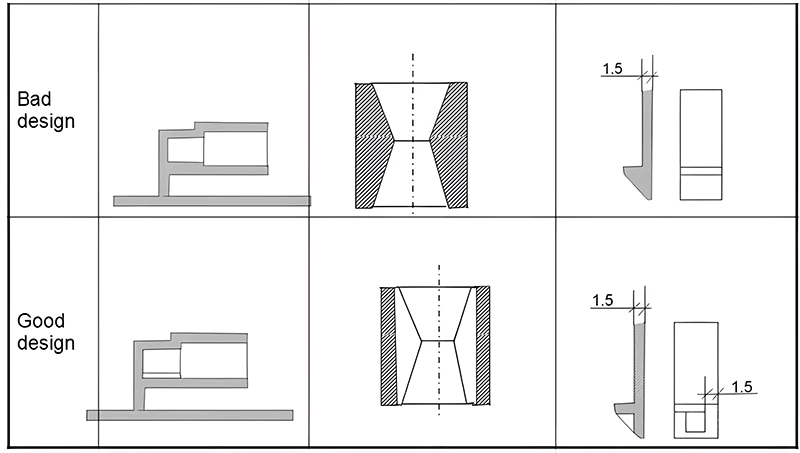
Uniformity of Wall Thickness
Uniform wall thickness is a key principle in plastic part design. Uneven thickness can cause inconsistent melt flow and cooling shrinkage, leading to defects like sink marks, voids, warping, or even cracking. It can also result in shrinkage marks, internal stresses, distortion, color variations, or differences in transparency. Thinner walls may compromise strength and rigidity during use and assembly. Economically, overly thick parts increase material costs and production time. Areas with thicker plastic cool slower, leading to sink marks. Figure 1 illustrates uniform wall thickness design.
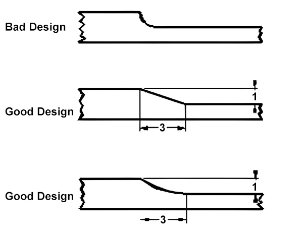
If a transition from thicker to thinner sections is unavoidable, it should be gradual, maintaining a maximum ratio of 3:1 in wall thickness, as shown in Figure 2.
In many cases, designers can use ribs to modify the overall wall thickness, which not only saves material and reduces production costs but also shortens cooling time. Cooling time is approximately proportional to wall thickness.
Additionally, designers must consider the flow path, the distance the molten material travels from the gate to all parts of the cavity. Generally, there’s a proportional relationship between flow path and wall thickness. A larger wall thickness means a longer flow path. If the ratio of flow path to wall thickness is too high, material shortage or incomplete filling can occur far from the gate. Therefore, increasing wall thickness might be necessary in some cases.
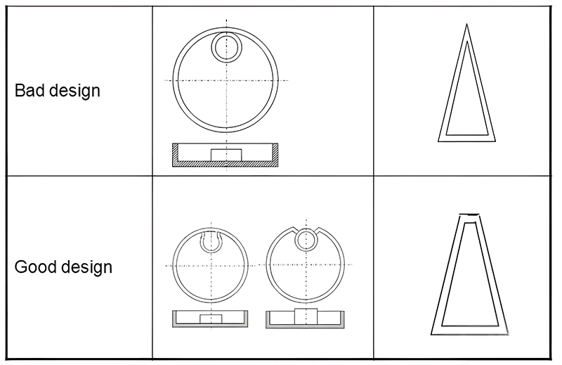
Sharp Angles
Sharp angles often lead to defects and stress concentration in parts. These areas are prone to unwanted material accumulation during post-processing treatments like electroplating or painting. Stress concentration can cause fractures under load or impact. Therefore, it’s advisable to avoid sharp angles in design. Figure 3 provides an example of sharp angle design.
Draft Angles and Ejection Direction Considerations
Ejection Direction and Parting Line
At the onset of designing an injection-molded product, it’s crucial to establish the ejection direction and parting line. This ensures minimal core-pulling mechanisms and reduces the impact of parting lines on the appearance. Once the ejection direction is set, structures like ribs, snaps, and protrusions should align with it to avoid core pulling, reduce seam lines, and extend mold life. The appropriate parting line can then be chosen to enhance appearance and performance.
During ejection from the mold, the part must overcome ejection and opening forces. Opening refers to the part’s detachment from the cavity. As the part cools inside the mold, it shrinks, causing the hole walls to grip the core tightly. Friction between the part and core, vacuum adhesion at the hole bottom, and other factors make ejection forces significantly greater than opening forces. Excessive ejection forces can deform the part, cause whitening, wrinkling, and surface abrasions.
Draft Angles
Draft angles are crucial in determining the magnitude of ejection forces. Since injection-molded parts often adhere to the convex mold due to cooling shrinkage, equal draft angles on both concave and convex molds ensure uniform wall thickness and prevent the part from sticking to the hotter concave mold after ejection. In special cases where the part is required to stick to the concave mold post-ejection, the draft angle on the adjoining concave part can be reduced, or an undercut can be deliberately added to the concave mold.
There’s no fixed value for draft angles; they are usually determined based on experience. Highly polished outer walls can have draft angles as small as 1/8 or 1/4 degree. For deeper or textured parts, the draft angle should increase correspondingly. Conventionally, an additional 1 degree of draft angle is required for every 0.025mm depth of texture.
Moreover, while larger draft angles generally facilitate easier ejection, it’s vital to maintain dimensional accuracy. The dimensional errors caused by draft angles must stay within the precision range. For parts with significant shrinkage or complex shapes, larger draft angles should be considered.
Ribs in Plastic Part Design
The strength of plastic parts does not solely depend on increased wall thickness. In fact, increased thickness can lead to internal stresses due to shrinkage, thereby reducing strength. The key to enhancing the strength of plastic parts lies in their stiffness. This is often achieved through a combination of thin-wall styles and strategically placed ribs to increase the section modulus.
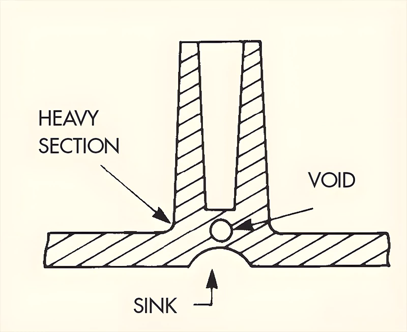
Rib Design Considerations
However, adding ribs results in increased thickness at the junction with the main wall. This thickness typically depends on the largest inscribed circle, determined by the rib thickness and the radius of the root fillet. With a base material thickness of 4mm, changing the rib thickness and root fillet radius alters the diameter of the largest inscribed circle. Figure 4 illustrates how local increases in wall thickness can lead to shrinkage deformation on the back, affecting the appearance. Proper design can reduce the likelihood of surface indentations, thus improving part quality.
From the analysis, it’s evident that the thickness of the rib should be minimized within limits. If the rib is too thin, its height must be increased to maintain stiffness. However, excessively thin ribs can lead to deformation under pressure, difficulties in filling during molding, and sticking to the mold. The radius of the rib’s base should not be too small to avoid stress concentration.
Generally, the radius of the rib’s root should be at least 40% of the rib thickness. The rib thickness should be between 50% and 75% of the base material’s wall thickness, with the higher ratio limited to materials with low shrinkage rates. The height of the rib should be less than five times the thickness of the base material. Ribs must have draft angles and be oriented in the direction of ejection or use movable mold components. The spacing between ribs should be more than twice the thickness of the base material.
To achieve uniform stiffness in all directions, the simplest method is to add ribs both longitudinally and transversely, intersecting at right angles. However, this can increase wall thickness at intersections, leading to greater shrinkage. A common solution is to add a round hole at the intersection to create uniform wall thickness, as shown in Figure 5.
Plastic Parts Design Considerations for Holes
1. Hole Placement and Strength
Incorporating holes in plastic parts for assembly or functionality is common. The size and placement of these holes should ideally not compromise the product’s strength or add complexity to the manufacturing process. Key factors to consider:
- The distance between adjacent holes or between a hole and the nearest edge should be at least equal to the diameter of the hole. This is particularly important for holes near edges to prevent fracture. For threaded holes, the distance from the hole to the edge of the product should generally be more than three times the diameter of the hole.
2. Types of Holes
There are various types of holes, such as through holes, blind holes, and stepped holes. From an assembly perspective, through holes are more common and easier to produce than blind holes. In terms of mold design, through holes are structurally more straightforward. They can be formed with cores fixed in both the movable and fixed parts of the mold, or with a single core in either part. The former creates two cantilever beams under the action of the molten plastic, but with short arms, resulting in minimal deformation.
The latter, generally forming a simply supported beam, also has minimal deformation. When using two cores, their diameters should differ slightly to prevent misalignment and ensure smooth mating surfaces. Blind holes, formed with a cantilever beam core, are more prone to bending under the impact of the molten plastic, leading to irregularly shaped holes. Generally, the depth of a blind hole should not exceed twice its diameter. For blind holes with diameters of 1.5mm or less, the depth should not exceed the diameter. The wall thickness at the bottom of a blind hole should be at least one-sixth of the hole diameter to avoid shrinkage.
3. Side Holes
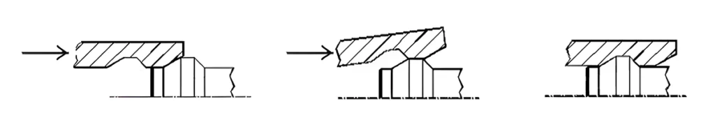
Side holes are typically formed using side cores, which can increase mold costs and maintenance, especially if the side cores are long and prone to breaking. If feasible, the design can be improved as shown in Figure 6, to mitigate these issues.

Bosses in Plastic Part Design
Bosses, typically protruding from the wall thickness, are used for assembling products, separating objects, and supporting other parts. Hollow bosses can accommodate inserts or tighten screws. These applications require sufficient strength to withstand pressure without cracking. Bosses are generally cylindrical, as this shape is easier to mold and offers better mechanical properties.
Integration with Structure
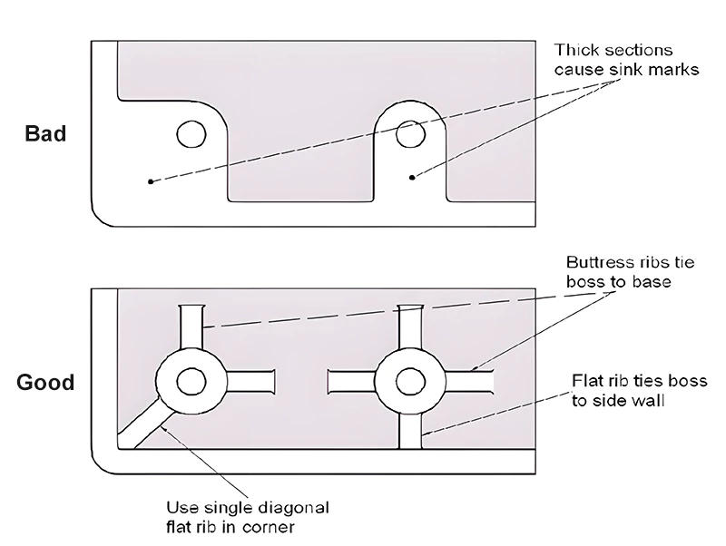
Ideally, bosses should not be designed as isolated cylinders. They should be connected to outer walls or used in conjunction with ribs. This approach enhances the strength of the boss and facilitates smoother flow of the plastic material. The connection to the outer wall should be a thin-wall connection to avoid shrinkage.
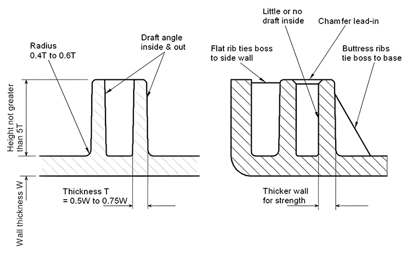
The base of the boss where it meets the base material should have a fillet radius of 0.4 to 0.6 times the thickness of the base material. The wall thickness of the boss should be between 0.5 and 0.75 times the thickness of the base material. The top of the boss should have a chamfer for ease of screw installation. Draft angles are also necessary on bosses. These design requirements are similar to those for ribs, making bosses a variant of ribs. Refer to Figures 7 and 8 for these relationships.
Threaded Bosses for Self-Tapping Screws
Many bosses are used to connect self-tapping screws. The internal threads on these bosses are formed through cold flow processing, which deforms the plastic without cutting it. The size of the threaded boss must be sufficient to withstand the screw’s insertion force and the load it carries. The hole diameter in the boss should ensure that the screw remains secure under specific torque and vibration conditions.
The outer diameter of the boss must withstand the circumferential force generated during screw tightening without breaking. To facilitate screw insertion, a recess is often created at the top of the boss, slightly larger than the nominal diameter of the thread. Calculating the dimensions of a boss can be complex.
A simplified estimation method from a foreign website is recommended, based on the nominal diameter of the screw. First, identify the material used, then apply the corresponding coefficient from the table to the screw’s nominal diameter to determine the appropriate size.
Snap-Fit Connections in Plastic Part Design
Snap-fit assembly is a convenient, cost-effective, and environmentally friendly method of connection. The snap-fit components are molded simultaneously with the product, eliminating the need for additional fasteners like screws. Assembly simply involves snapping the corresponding parts together.
The principle of a snap-fit involves pushing a protruding part of one component past an obstacle on another component. This process involves elastic deformation, and once the obstacle is cleared, the parts snap back into their original shape and lock together, as shown in Figure 9. Snap-fit connections can be either permanent or releasable.
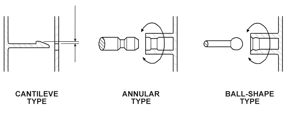
Structurally, snap-fits can be categorized into cantilever, annular, and ball shape, as detailed in Figure 10.
Key Angles and Calculations
1. Critical Angles
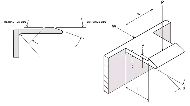
Two critical angles in snap-fit design are the retraction side and the entrance side. Generally, a larger retraction side is preferred for a more secure fit. When the retraction side approaches 90 degrees, the snap-fit becomes permanent, as shown in Figure 11.
2. Calculations for Snap-Fits
The maximum allowable deflection for a uniform section snap-fit can be calculated using: Y = el² / (1.5t). This formula assumes deformation only in the snap hook. In practice, some deformation also occurs near the snap-fit, which can be considered a safety factor.
The force required to produce a deflection Y in the snap-fit: P = wt²Ee / (6l).
The assembly force can be estimated with: W = P(μ + tga) / (1 – tga).
For releasable snap-fits, the release force can be calculated using the same formulas, substituting angle a with angle b.
Table 2 provides some coefficients needed for these calculations.
| Materials | (e)(%) | GPa | Coefficient(s) of Friction |
| PS | 2 | 3.0 | 0.3 |
| ABS | 2 | 2.1 | 0.2 |
| SAN | 2 | 3.6 | 0.3 |
| PMMA | 2 | 2.9 | 0.4 |
| LDPE | 5 | 0.2 | 0.3 |
| HDPE | 4 | 1.2 | 0.3 |
| PP | 4 | 1.3 | 0.3 |
| PA | 3 | 1.2 | 0.1 |
| POM | 4 | 2.6 | 0.4 |
| PC | 2 | 2.8 | 0.4 |
3. Annular Snap-Fits
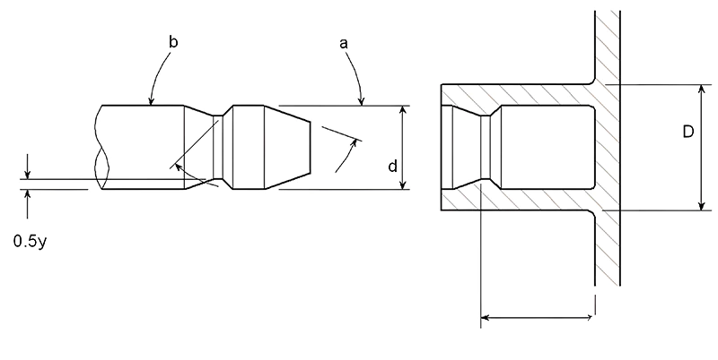
Annular snap-fits use a ring’s internal protrusions to engage with a shaft’s groove. Based on the release angle, they can be either releasable or non-releasable. The ring expands elastically during insertion and removal, typically made from materials with good elasticity.
Figure 12 illustrates an annular snap-fit.
The maximum size of the annular snap-fit’s protrusion can be calculated using:
y = Sd((K + v) / E + (1 – v) / E) / K
Where S is the design stress, v is Poisson’s ratio, E is the elastic modulus, and K is a geometric coefficient calculated as: K = (1 + (d/D)²) / (1 – (d/D)²).
The expansion force on the sleeve can be calculated with:
P = (tan a + μ) / Sydlπ / K
Where μ is the coefficient of friction.
Table 2 provides Poisson’s ratios for various unfilled materials, with friction coefficients shown in Figure 17.
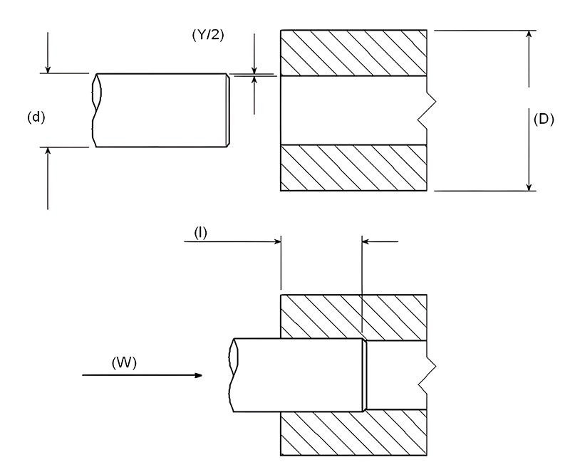
Interference Fits in Plastic Part Design
Interference fits, used to connect holes and shafts, are effective for transmitting torque and other forces. This type of connection is convenient and straightforward. The primary consideration in designing interference fits is the amount of interference: too little interference leads to unreliable connections, while too much makes assembly difficult and increases the risk of cracking.
When designing interference fits, it’s important to consider the tolerances of the hole and shaft, as well as the operating temperature, since temperature variations can significantly affect the interference amount. Most shafts are metallic, and to ensure a reliable connection, it’s common to add knurling or grooves on the mating shaft. The general formula for calculating interference is:
Y = Sd((K + v) / E) / K
Where S is the design stress, v is Poisson’s ratio, E is the elastic modulus, and K is a geometric coefficient calculated as:
K = (1 + (d/D)²) / (1 – (d/D)²)
The assembly force can be calculated with:
W = Sdlπμ / K
Where μ is the coefficient of friction, and l is the length of engagement. The Poisson’s ratio can be found in Table 3.
| Materials | Poisson’s Ratio |
| PS | 0.38 |
| PMMA | 0.4 |
| LDPE | 0.49 |
| HDPE | 0.47 |
| PP | 0.43 |
| PA | 0.45 |
| PC | 0.42 |
| PVC | 0.42 |
| PPO | 0.41 |
| PPS | 0.42 |
| Steel | 0.38 |
In addition to interference fits, other methods for joining plastic parts include heat staking, welding, and ultrasonic welding. Each of these methods has its own set of advantages and is suitable for different applications based on the material properties and the requirements of the assembly.
Tolerance Impact and Material Selection in Plastic Part Design
Most plastic products can achieve high precision in dimensional tolerances. However, materials with high shrinkage rates or softer materials can be more challenging to control. Product design must consider the use environment, plastic material, and product shape to set appropriate tolerances. As customer demands increase, the concept of fit and finish must evolve. The goal is to achieve a balance between fit, precision, and aesthetics.
Injection molding is generally categorized into three quality levels: general-purpose, medium precision, and high precision.
- General-Purpose Molding: This requires a lower level of quality control, characterized by lower rejection rates and faster production cycles.
- Medium Precision Molding: More expensive due to higher demands on molds and production processes, requiring frequent quality checks.
- High Precision Molding: Demands accurate molds, optimal production conditions, and continuous production monitoring. This impacts the production cycle, increasing unit production and quality control costs. Designers must balance between precision and economic production costs, often relaxing tolerances for non-critical dimensions while meeting performance, appearance, and fit requirements.
Material Selection
There are no inherently bad materials, only inappropriate choices for specific applications. Designers must thoroughly understand the properties of available materials and carefully test them to study their impact on the performance of molded products.
The most commonly used materials in injection molding are thermoplastics, which are divided into amorphous and semi-crystalline plastics. These two categories differ significantly in molecular structure and performance affected by crystallization. Semi-crystalline thermoplastics are typically used for parts requiring high mechanical strength, while amorphous thermoplastics, less prone to bending, are often used for casings.
Thermoplastics are available in unreinforced, glass fiber reinforced, and mineral or glass bead filled varieties. Glass fibers mainly enhance strength, rigidity, and temperature resistance; minerals and glass fibers reduce warping but offer lower reinforcement. Specific changes in properties due to reinforcements should be confirmed with material suppliers or through experimentation.
Some thermoplastics, especially PA6 and PA66, are highly hygroscopic, which can significantly affect their mechanical properties and dimensional stability.
Considerations related to processing and assembly are crucial. Integrating multiple functions into a single component can save on costly assembly expenses. This principle is beneficial for calculating production costs. High-performance materials (rigidity, toughness) can allow for thinner walls, shortening production cycles. Therefore, listing all standards and systematically evaluating them is essential.
Fillets and Rounded Corners in Plastic Part Design
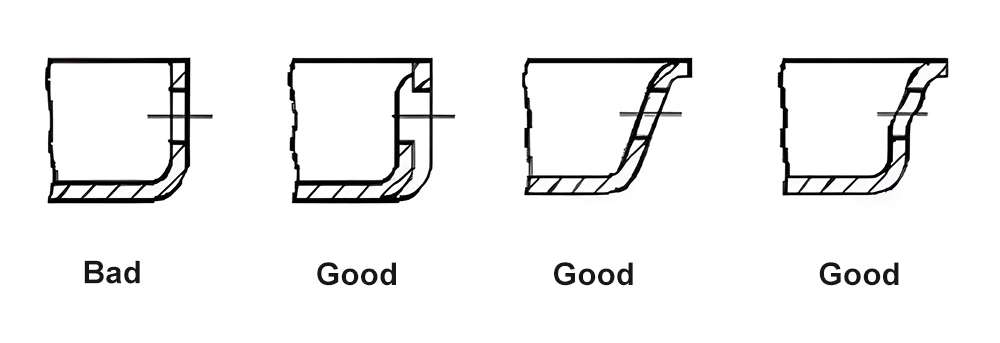
Sharp corners often lead to defects and stress concentration in plastic parts, which can cause fractures under load or impact. Larger rounded corners (fillets) offer a solution to this problem. They not only reduce stress concentration but also facilitate smoother flow of the plastic during molding and easier ejection of the finished product.
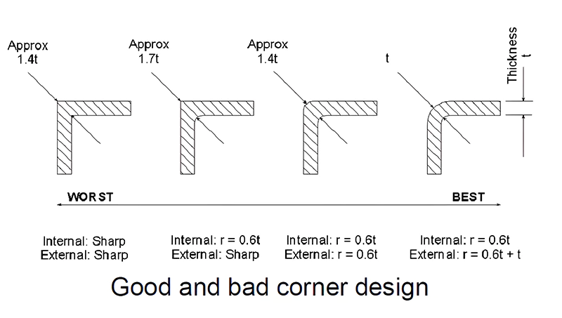
If the internal corner is rounded and the external corner is sharp, the area at the turn will still be thicker than other parts, leading to shrinkage. A solution is to round both internal and external corners to achieve uniform wall thickness. In this case, the external radius is the sum of the internal radius and the base wall thickness.
The design principles for corner radii also apply to cantilever snap-fits. In these snap-fits, the cantilever arm needs to bend and fit into place. If the radius of the corner (R) is too small, it can lead to excessive stress concentration, making the product prone to breaking when bent. Conversely, if R is too large, it can result in shrinkage marks and voids. Therefore, there is a specific ratio between the corner radius and wall thickness, typically ranging from 0.2 to 0.6, with an ideal value around 0.5.
Conclusion
In summary, this article has covered various critical aspects of structural design for injection molded parts, including wall thickness, draft angles, ribs, holes, bosses, snap-fits, interference fits, tolerances, and rounded corners. Each of these elements plays a vital role in the overall functionality, durability, and quality of the final product.
However, it’s important to remember that structural design is also influenced by environmental factors, specific conditions, and unique requirements of each project. These factors necessitate a tailored approach to each design challenge.
The goal of this comprehensive overview is to equip aspiring and practicing structural design engineers with the knowledge and insights needed to excel in their field. By understanding and applying these principles, designers can create more effective, reliable, and high-quality injection molded parts.


One Response
Your blog is always a highlight of my day