Los diseñadores de productos experimentados conocen a fondo los procesos de moldeo por inyección y tienen en cuenta numerosos factores en el diseño de piezas de plástico. Este artículo se centra en elementos esenciales como el grosor de la pared, los ángulos de desmoldeo, las nervaduras, los orificios, los pilares, los encajes, los ajustes de interferencia y las tolerancias en el diseño de piezas moldeadas de plástico.
Espesor de pared en el diseño de piezas de plástico
Determinar el grosor de pared adecuado es crucial. Otras características, como las nervaduras y los filetes, hacen referencia al grosor de la pared. El grosor de la pared de un producto de plástico depende de varios requisitos, como las fuerzas externas que debe soportar, el soporte para otras piezas, las propiedades del material plástico, el peso, el rendimiento eléctrico, la precisión dimensional, la estabilidad y los requisitos de montaje.
Normalmente, el grosor de pared de los materiales termoplásticos oscila entre 1 y 6 mm, siendo de 2 a 3 mm lo más habitual. Para piezas más grandes, los espesores pueden superar los 6 mm. La tabla 1 muestra los valores recomendados para el grosor de pared de diversos termoplásticos.
| Materiales | Espesor mínimo de pared | Valores recomendados para piezas pequeñas | Valores recomendados para piezas medianas | Valores recomendados para piezas grandes |
| Nylon | 0.45 | 0.76 | 1.5 | 2.4~3.2 |
| PE | 0.6 | 1.25 | 1.6 | 2.4~3.2 |
| PS | 0.75 | 1.25 | 1.6 | 3.2~5.4 |
| PMMA | 0.8 | 1.5 | 2.2 | 4~6.5 |
| PVC | 1.2 | 1.6 | 1.8 | 3.2~5.8 |
| PP | 0.85 | 1.54 | 1.75 | 2.4~3.2 |
| PC | 0.95 | 1.8 | 2.3 | 3~4.5 |
| POM | 0.8 | 1.4 | 1.6 | 3.2~5.4 |
| ABS | 0.8 | 1 | 2.3 | 3.2~6 |
Uniformidad del espesor de pared
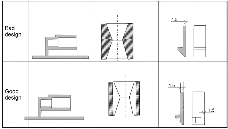
El grosor uniforme de las paredes es un principio clave en el diseño de piezas de plástico. Un grosor desigual puede provocar un flujo de fusión y una contracción por enfriamiento incoherentes, lo que da lugar a defectos como marcas de hundimiento, huecos, alabeos o incluso grietas. También puede dar lugar a marcas de contracción, tensiones internas, distorsión, variaciones de color o diferencias de transparencia. Las paredes más finas pueden comprometer la resistencia y la rigidez durante el uso y el montaje. Económicamente, las piezas demasiado gruesas aumentan los costes de material y el tiempo de producción. Las zonas con plástico más grueso se enfrían más lentamente, lo que provoca marcas de hundimiento. La figura 1 ilustra el diseño de espesores de pared uniformes.
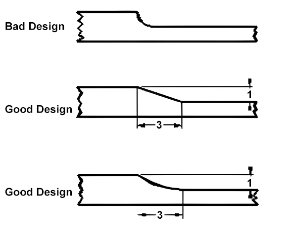
Si es inevitable pasar de secciones más gruesas a otras más delgadas, la transición debe ser gradual, manteniendo una relación máxima de 3:1 en el espesor de la pared, como se muestra en la figura 2.
En muchos casos, los diseñadores pueden utilizar nervios para modificar el grosor total de la pared, lo que no sólo ahorra material y reduce los costes de producción, sino que también acorta el tiempo de enfriamiento. El tiempo de enfriamiento es aproximadamente proporcional al grosor de la pared.
Además, los diseñadores deben tener en cuenta el recorrido del flujo, es decir, la distancia que recorre el material fundido desde la compuerta hasta todas las partes de la cavidad. Por lo general, existe una relación proporcional entre el recorrido del flujo y el grosor de la pared. A mayor grosor de pared, mayor recorrido del flujo. Si la relación entre el recorrido del flujo y el grosor de la pared es demasiado alta, puede producirse una escasez de material o un llenado incompleto lejos de la compuerta. Por lo tanto, en algunos casos puede ser necesario aumentar el grosor de la pared.
Ángulos agudos
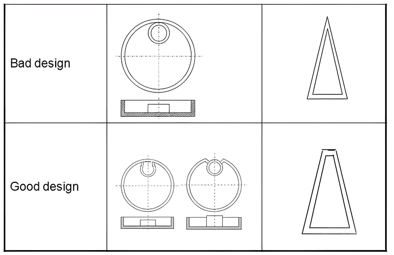
Los ángulos agudos suelen provocar defectos y concentración de tensiones en las piezas. Estas zonas son propensas a acumular material no deseado durante los tratamientos posteriores, como la galvanoplastia o la pintura. La concentración de tensiones puede provocar fracturas bajo carga o impacto. Por tanto, es aconsejable evitar los ángulos agudos en el diseño. La figura 3 muestra un ejemplo de diseño de ángulos agudos.
Ángulos de inclinación y dirección de eyección
Dirección de eyección y línea de separación
Al principio del diseño de un producto moldeado por inyección, es fundamental establecer la dirección de eyección y la línea de separación. Esto garantiza unos mecanismos de extracción del núcleo mínimos y reduce el impacto de las líneas de separación en el aspecto. Una vez establecida la dirección de expulsión, las estructuras como nervaduras, broches y protuberancias deben alinearse con ella para evitar la tracción del núcleo, reducir las líneas de costura y prolongar la vida útil del molde. A continuación, puede elegirse la línea de apertura adecuada para mejorar el aspecto y el rendimiento.
Durante la expulsión del molde, la pieza debe superar las fuerzas de expulsión y apertura. La apertura se refiere al desprendimiento de la pieza de la cavidad. A medida que la pieza se enfría dentro del molde, se contrae, lo que hace que las paredes del orificio se agarren firmemente al núcleo. La fricción entre la pieza y el núcleo, la adherencia del vacío en el fondo del orificio y otros factores hacen que las fuerzas de expulsión sean significativamente mayores que las fuerzas de apertura. Unas fuerzas de expulsión excesivas pueden deformar la pieza, provocar blanqueamiento, arrugas y abrasiones en la superficie.
Ángulos de calado
Los ángulos de desmoldeo son cruciales para determinar la magnitud de las fuerzas de expulsión. Dado que las piezas moldeadas por inyección suelen adherirse al molde convexo debido a la contracción por enfriamiento, unos ángulos de desmoldeo iguales en los moldes cóncavos y convexos garantizan un grosor de pared uniforme y evitan que la pieza se adhiera al molde cóncavo más caliente después de la expulsión. En casos especiales en los que se requiera que la pieza se adhiera al molde cóncavo tras la expulsión, puede reducirse el ángulo de desmoldeo de la pieza cóncava adyacente, o puede añadirse deliberadamente un rebaje al molde cóncavo.
No hay un valor fijo para los ángulos de desmoldeo; suelen determinarse en función de la experiencia. Las paredes exteriores muy pulidas pueden tener ángulos de desmoldeo de tan sólo 1/8 o 1/4 de grado. Para piezas más profundas o texturizadas, el ángulo de inclinación debe aumentar proporcionalmente. Convencionalmente, se requiere 1 grado adicional de ángulo de desmoldeo por cada 0,025 mm de profundidad de textura.
Además, aunque los ángulos de desmoldeo mayores suelen facilitar la expulsión, es vital mantener la precisión dimensional. Los errores dimensionales provocados por los ángulos de desmoldeo deben mantenerse dentro del margen de precisión. Para piezas con una contracción significativa o formas complejas, deben considerarse ángulos de desmoldeo mayores.
Costillas en el diseño de piezas de plástico
La resistencia de las piezas de plástico no depende únicamente del aumento del grosor de las paredes. De hecho, un mayor grosor puede provocar tensiones internas debidas a la contracción, reduciendo así la resistencia. La clave para aumentar la resistencia de las piezas de plástico reside en su rigidez. Esto se consigue a menudo mediante una combinación de estilos de pared delgada y nervaduras colocadas estratégicamente para aumentar el módulo de sección.
Consideraciones sobre el diseño de las costillas
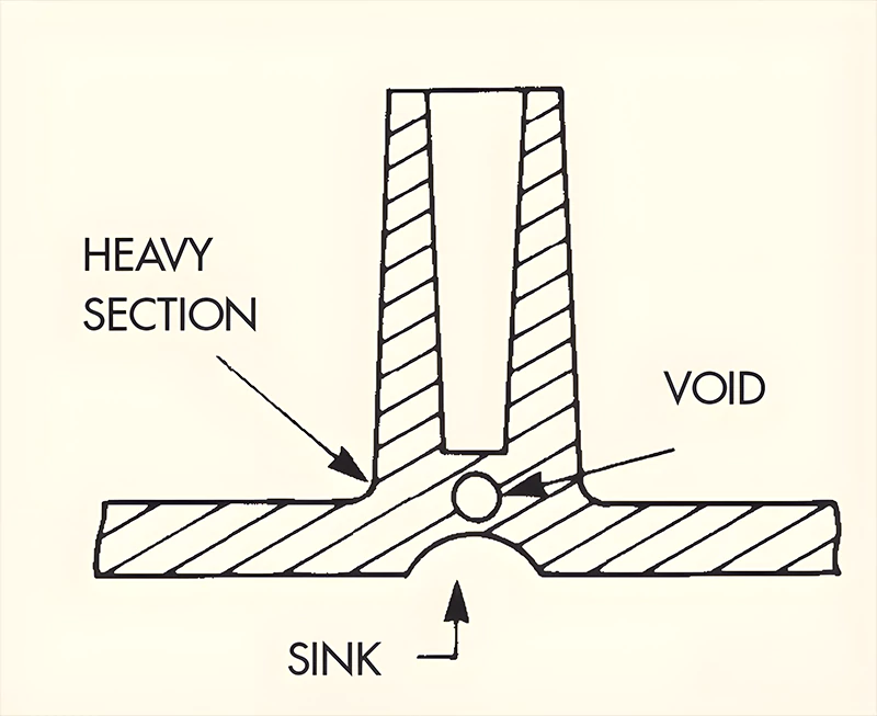
Sin embargo, la adición de nervaduras da lugar a un aumento del espesor en la unión con la pared principal. Este grosor suele depender del círculo inscrito mayor, determinado por el grosor de la nervadura y el radio del filete de raíz. Con un grosor del material base de 4 mm, el cambio del grosor de las nervaduras y del radio del filete de raíz altera el diámetro del círculo inscrito mayor. La figura 4 ilustra cómo los aumentos locales del grosor de la pared pueden provocar deformaciones por contracción en el dorso, lo que afecta al aspecto. Un diseño adecuado puede reducir la probabilidad de que se produzcan hendiduras en la superficie, mejorando así la calidad de la pieza.
Del análisis se desprende que el grosor de la costilla debe minimizarse dentro de unos límites. Si la costilla es demasiado fina, hay que aumentar su altura para mantener la rigidez. Sin embargo, unas nervaduras excesivamente finas pueden provocar deformaciones bajo presión, dificultades de llenado durante el moldeo y adherencia al molde. El radio de la base de la nervadura no debe ser demasiado pequeño para evitar la concentración de tensiones.
En general, el radio de la raíz de la costilla debe ser al menos 40% del grosor de la costilla. El grosor de la nervadura debe estar comprendido entre 50% y 75% del grosor de la pared del material base, limitándose la proporción más alta a materiales con bajos índices de contracción. La altura del nervio debe ser inferior a cinco veces el espesor del material base. Las nervaduras deben tener ángulos de desmoldeo y estar orientadas en la dirección de expulsión o utilizar componentes móviles del molde. La separación entre costillas debe ser superior a dos veces el espesor del material base.
Para conseguir una rigidez uniforme en todas las direcciones, el método más sencillo consiste en añadir nervios tanto longitudinal como transversalmente, que se crucen en ángulo recto. Sin embargo, esto puede aumentar el grosor de la pared en las intersecciones, provocando una mayor contracción. Una solución habitual es añadir un orificio redondo en la intersección para crear un espesor de pared uniforme, como se muestra en la figura 5.
Consideraciones sobre el diseño de agujeros en piezas de plástico
1. Colocación y resistencia de los orificios
La incorporación de orificios en piezas de plástico para su montaje o funcionalidad es habitual. Lo ideal es que el tamaño y la ubicación de estos orificios no comprometan la resistencia del producto ni añadan complejidad al proceso de fabricación. Factores clave a tener en cuenta:
- La distancia entre orificios adyacentes o entre un orificio y el borde más cercano debe ser al menos igual al diámetro del orificio. Esto es especialmente importante en el caso de los orificios cercanos a los bordes para evitar fracturas. En el caso de los orificios roscados, la distancia entre el orificio y el borde del producto debe ser, por lo general, más de tres veces el diámetro del orificio.
2. Tipos de agujeros
Hay varios tipos de agujeros, como los pasantes, agujeros ciegosy agujeros escalonados. Desde el punto de vista del montaje, los orificios pasantes son más comunes y fáciles de producir que los ciegos. Desde el punto de vista del diseño del molde, los agujeros pasantes son estructuralmente más sencillos. Pueden formarse con núcleos fijados tanto en la parte móvil como en la fija del molde, o con un solo núcleo en cualquiera de las dos partes. El primero crea dos vigas en voladizo bajo la acción del plástico fundido, pero con brazos cortos, lo que provoca una deformación mínima.
Este último, que suele formar una viga simplemente apoyada, también presenta una deformación mínima. Cuando se utilizan dos núcleos, sus diámetros deben diferir ligeramente para evitar desalineaciones y garantizar superficies de contacto lisas. Los agujeros ciegos, formados con un núcleo de viga en voladizo, son más propensos a doblarse bajo el impacto del plástico fundido, lo que da lugar a agujeros de forma irregular. Por lo general, la profundidad de un agujero ciego no debe superar el doble de su diámetro. Para agujeros ciegos con diámetros de 1,5 mm o menos, la profundidad no debe superar el diámetro. El grosor de la pared en la parte inferior de un orificio ciego debe ser al menos una sexta parte del diámetro del orificio para evitar la contracción.
3. Orificios laterales
Los orificios laterales suelen formarse utilizando machos laterales, lo que puede aumentar los costes del molde y el mantenimiento, especialmente si los machos laterales son largos y propensos a romperse. Si es factible, el diseño puede mejorarse como se muestra en la Figura 6, para mitigar estos problemas.

Salientes en el diseño de piezas de plástico
Jefes, que suelen sobresalir del grosor de la pared, se utilizan para ensamblar productos, separar objetos y soportar otras piezas. Los resaltes huecos pueden alojar insertos o apretar tornillos. Estas aplicaciones requieren una resistencia suficiente para soportar la presión sin agrietarse. Los salientes suelen ser cilíndricos, ya que esta forma es más fácil de moldear y ofrece mejores propiedades mecánicas.
Integración con la estructura
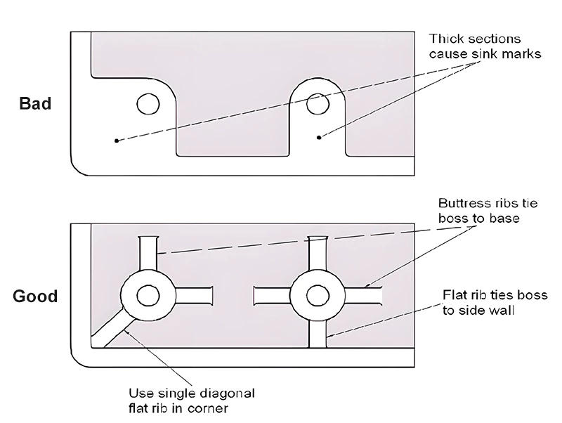
Lo ideal es que los resaltes no se diseñen como cilindros aislados. Deben conectarse a las paredes exteriores o utilizarse junto con nervaduras. Este enfoque aumenta la resistencia del saliente y facilita un flujo más suave del material plástico. La conexión a la pared exterior debe ser una conexión de pared delgada para evitar la contracción.
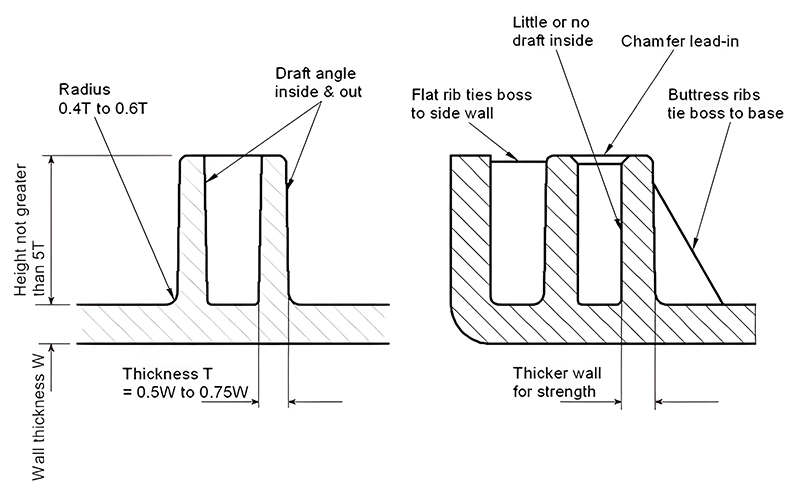
La base del resalte, donde se une con el material base, debe tener un radio de redondeo de 0,4 a 0,6 veces el espesor del material base. El grosor de la pared del resalte debe ser entre 0,5 y 0,75 veces el grosor del material base. La parte superior del resalte debe tener un chaflán para facilitar la instalación de los tornillos. También son necesarios ángulos de inclinación en los resaltes. Estos requisitos de diseño son similares a los de las costillas, por lo que los resaltes son una variante de las costillas. Consulte estas relaciones en las figuras 7 y 8.
Tapones roscados para tornillos autorroscantes
Muchos resaltes se utilizan para conectar tornillos autorroscantes. Las roscas internas de estos salientes se forman mediante un proceso de flujo en frío, que deforma el plástico sin cortarlo. El tamaño del saliente roscado debe ser suficiente para soportar la fuerza de inserción del tornillo y la carga que soporta. El diámetro del orificio en el saliente debe garantizar que el tornillo permanezca seguro en condiciones específicas de par y vibración.
El diámetro exterior del resalte debe soportar sin romperse la fuerza circunferencial generada durante el apriete del tornillo. Para facilitar la inserción del tornillo, a menudo se crea un rebaje en la parte superior del resalte, ligeramente mayor que el diámetro nominal de la rosca. El cálculo de las dimensiones de un inserto puede ser complejo.
Se recomienda un método de estimación simplificado de un sitio web extranjero, basado en el diámetro nominal del tornillo. En primer lugar, identifique el material utilizado y, a continuación, aplique el coeficiente correspondiente de la tabla al diámetro nominal del tornillo para determinar el tamaño adecuado.
Conexiones Snap-Fit en el diseño de piezas de plástico
El montaje a presión es un método de conexión cómodo, rentable y respetuoso con el medio ambiente. Los componentes snap-fit se moldean simultáneamente con el producto, eliminando la necesidad de elementos de fijación adicionales como tornillos. El montaje consiste simplemente en encajar las piezas correspondientes.
El principio del encaje a presión consiste en empujar una parte saliente de un componente para que supere un obstáculo en otro componente. Este proceso implica una deformación elástica y, una vez superado el obstáculo, las piezas vuelven a su forma original y se encajan entre sí, como se muestra en la figura 9. Las conexiones a presión pueden ser permanentes o liberables. Las conexiones a presión pueden ser permanentes o liberables.
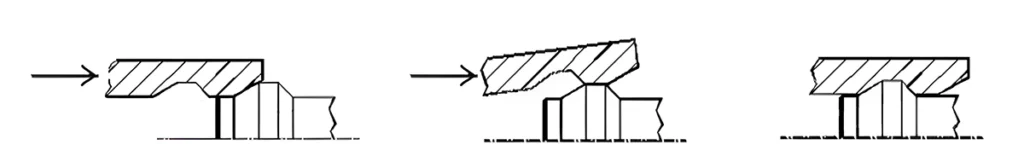
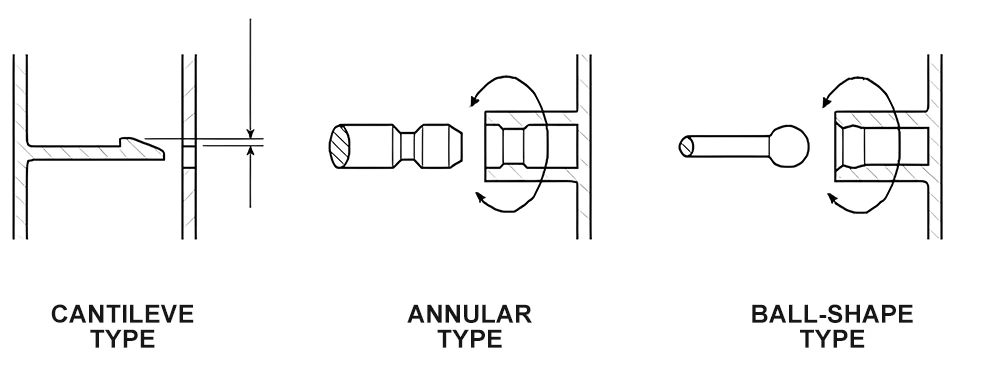
Estructuralmente, los encajes a presión pueden clasificarse en voladizo, anular y esférico, como se detalla en la figura 10.
Ángulos clave y cálculos
1. Ángulos críticos
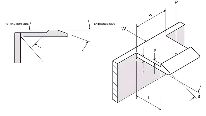
Dos ángulos críticos en el diseño de los encajes a presión son el lado de retracción y el lado de entrada. Generalmente, se prefiere un lado de retracción mayor para un ajuste más seguro. Cuando el lado de retracción se aproxima a 90 grados, el ajuste a presión se vuelve permanente, como se muestra en la figura 11.
2. Cálculos para Snap-Fits
La deformación máxima admisible para un ajuste a presión de sección uniforme puede calcularse mediante: Y = el² / (1,5t). Esta fórmula supone una deformación sólo en el mosquetón. En la práctica, también se produce cierta deformación cerca del mosquetón, lo que puede considerarse un factor de seguridad.
La fuerza necesaria para producir una desviación Y en el encaje a presión: P = wt²Ee / (6l).
La fuerza de ensamblaje se puede estimar con: W = P(μ + tga) / (1 - tga).
Para los encajes a presión liberables, la fuerza de liberación puede calcularse utilizando las mismas fórmulas, sustituyendo el ángulo a por el ángulo b.
En el cuadro 2 figuran algunos coeficientes necesarios para estos cálculos.
| Materiales | (e)(%) | GPa | Coeficiente(s) de fricción |
| PS | 2 | 3.0 | 0.3 |
| ABS | 2 | 2.1 | 0.2 |
| SAN | 2 | 3.6 | 0.3 |
| PMMA | 2 | 2.9 | 0.4 |
| LDPE | 5 | 0.2 | 0.3 |
| HDPE | 4 | 1.2 | 0.3 |
| PP | 4 | 1.3 | 0.3 |
| PA | 3 | 1.2 | 0.1 |
| POM | 4 | 2.6 | 0.4 |
| PC | 2 | 2.8 | 0.4 |
3. Snap-Fits anulares
Los cierres rápidos anulares utilizan las protuberancias internas de un anillo para encajar en la ranura de un eje. En función del ángulo de liberación, pueden ser liberables o no liberables. El anillo se expande elásticamente durante la inserción y la extracción, y suele estar fabricado con materiales de buena elasticidad.
La figura 12 ilustra un encaje a presión anular.
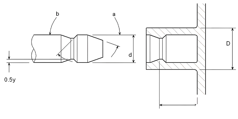
El tamaño máximo de la protuberancia del ajuste a presión anular puede calcularse utilizando:
y = Sd((K + v) / E + (1 - v) / E) / K
Donde S es la tensión de diseño, v es la relación de Poisson, E es el módulo elástico y K es un coeficiente geométrico calculado como: K = (1 + (d/D)²) / (1 - (d/D)²).
La fuerza de dilatación sobre el manguito puede calcularse con:
P = (tan a + μ) / Sydlπ / K
Donde μ es el coeficiente de rozamiento.
La Tabla 2 proporciona los coeficientes de Poisson para varios materiales sin relleno, con los coeficientes de fricción mostrados en la Figura 17.
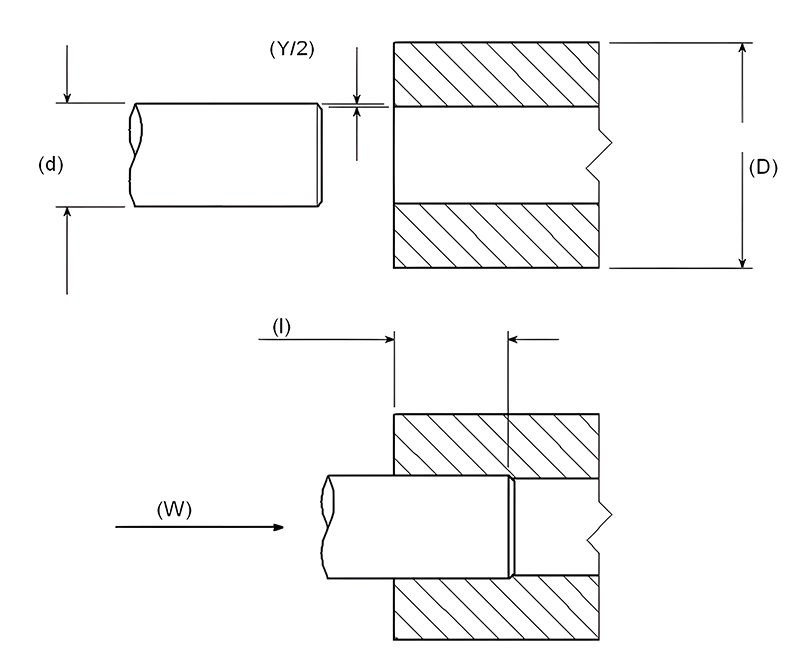
Ajustes por interferencia en el diseño de piezas de plástico
Los ajustes de interferencia, utilizados para conectar orificios y ejes, son eficaces para transmitir par y otras fuerzas. Este tipo de conexión es cómoda y sencilla. La principal consideración a la hora de diseñar los ajustes por interferencia es la cantidad de interferencia: una interferencia demasiado pequeña da lugar a conexiones poco fiables, mientras que una interferencia demasiado grande dificulta el montaje y aumenta el riesgo de grietas.
Al diseñar los ajustes por interferencia, es importante tener en cuenta las tolerancias del orificio y el eje, así como la temperatura de funcionamiento, ya que las variaciones de temperatura pueden afectar significativamente a la cantidad de interferencia. La mayoría de los ejes son metálicos y, para garantizar una conexión fiable, es habitual añadir estrías o ranuras en el eje de acoplamiento. La fórmula general para calcular la interferencia es:
Y = Sd((K + v) / E) / K
Donde S es la tensión de diseño, v es la relación de Poisson, E es el módulo elástico y K es un coeficiente geométrico calculado como:
K = (1 + (d/D)²) / (1 - (d/D)²)
La fuerza de montaje se puede calcular con:
W = Sdlπμ / K
Donde μ es el coeficiente de fricción, y l es la longitud de enganche. La relación de Poisson se puede encontrar en la Tabla 3.
| Materiales | Relación de Poisson |
| PS | 0.38 |
| PMMA | 0.4 |
| LDPE | 0.49 |
| HDPE | 0.47 |
| PP | 0.43 |
| PA | 0.45 |
| PC | 0.42 |
| PVC | 0.42 |
| PPO | 0.41 |
| PPS | 0.42 |
| Acero | 0.38 |
Además de los ajustes por interferencia, otros métodos para unir piezas de plástico son el termoestañado, la soldadura y la soldadura por ultrasonidos. Cada uno de estos métodos tiene sus propias ventajas y es adecuado para distintas aplicaciones en función de las propiedades del material y los requisitos del ensamblaje.
Impacto de la tolerancia y selección de materiales en el diseño de piezas de plástico
La mayoría de los productos de plástico pueden alcanzar una gran precisión en las tolerancias dimensionales. Sin embargo, los materiales con altos índices de contracción o los materiales más blandos pueden ser más difíciles de controlar. El diseño del producto debe tener en cuenta el entorno de uso, el material plástico y la forma del producto para establecer las tolerancias adecuadas. A medida que aumentan las exigencias de los clientes, el concepto de ajuste y acabado debe evolucionar. El objetivo es lograr un equilibrio entre ajuste, precisión y estética.
El moldeo por inyección se suele clasificar en tres niveles de calidad: uso general, precisión media y alta precisión.
- Moldeo de uso general: Esto requiere un menor nivel de control de calidad, caracterizado por tasas de rechazo más bajas y ciclos de producción más rápidos.
- Moldeo de precisión media: Más caro debido a las mayores exigencias a los moldes y procesos de producción, que requieren frecuentes controles de calidad.
- Moldeo de alta precisión: Exige moldes precisos, condiciones de producción óptimas y una supervisión continua de la producción. Esto repercute en el ciclo de producción, aumentando los costes unitarios de producción y de control de calidad. Los diseñadores deben encontrar un equilibrio entre precisión y costes de producción económicos, relajando a menudo las tolerancias de las dimensiones no críticas y cumpliendo al mismo tiempo los requisitos de rendimiento, aspecto y ajuste.
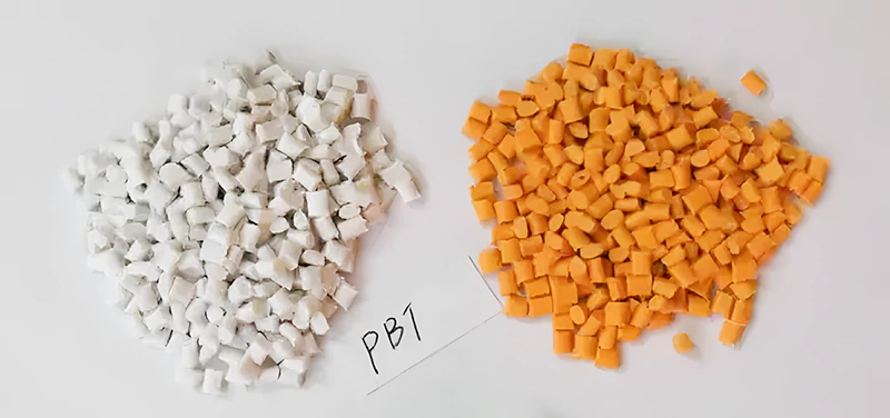
Selección de materiales
No hay materiales intrínsecamente malos, sólo elecciones inadecuadas para aplicaciones específicas. Los diseñadores deben conocer a fondo las propiedades de los materiales disponibles y probarlos cuidadosamente para estudiar su impacto en el rendimiento de los productos moldeados.
Los materiales más utilizados en el moldeo por inyección son los termoplásticos, que se dividen en plásticos amorfos y semicristalinos. Estas dos categorías difieren significativamente en la estructura molecular y el rendimiento afectado por la cristalización. Los termoplásticos semicristalinos se suelen utilizar para piezas que requieren una gran resistencia mecánica, mientras que los termoplásticos amorfos, menos propensos a la flexión, se suelen emplear para carcasas.
Los termoplásticos están disponibles sin reforzar, reforzados con fibra de vidrio y rellenos de perlas minerales o de vidrio. Las fibras de vidrio mejoran principalmente la resistencia, la rigidez y la resistencia a la temperatura; los minerales y las fibras de vidrio reducen el alabeo pero ofrecen un menor refuerzo. Los cambios específicos en las propiedades debidos a los refuerzos deben confirmarse con los proveedores de materiales o mediante experimentación.
Algunos termoplásticos, especialmente la PA6 y la PA66, son muy higroscópicos, lo que puede afectar significativamente a sus propiedades mecánicas y a su estabilidad dimensional.
Las consideraciones relacionadas con la transformación y el montaje son cruciales. Integrar varias funciones en un solo componente puede ahorrar costosos gastos de montaje. Este principio es beneficioso para calcular los costes de producción. Los materiales de alto rendimiento (rigidez, tenacidad) pueden permitir paredes más finas, lo que acorta los ciclos de producción. Por tanto, es esencial enumerar todas las normas y evaluarlas sistemáticamente.
Filetes y esquinas redondeadas en el diseño de piezas de plástico
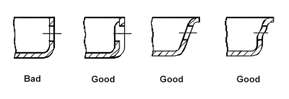
Las esquinas afiladas suelen provocar defectos y concentración de tensiones en las piezas de plástico, lo que puede causar fracturas bajo carga o impacto. Las esquinas redondeadas más grandes (filetes) ofrecen una solución a este problema. No sólo reducen la concentración de tensiones, sino que también facilitan un flujo más suave del plástico durante el moldeo y una expulsión más fácil del producto acabado.
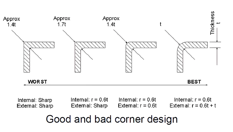
Si la esquina interna está redondeada y la externa es afilada, la zona del giro seguirá siendo más gruesa que otras partes, lo que provocará la contracción. Una solución es redondear tanto las esquinas internas como las externas para conseguir un grosor de pared uniforme. En este caso, el radio exterior es la suma del radio interior y el grosor de la pared base.
Los principios de diseño de los radios de las esquinas también se aplican a los encajes a presión en voladizo. En estos casos, el brazo en voladizo debe doblarse y encajar en su sitio. Si el radio de la esquina (R) es demasiado pequeño, puede provocar una concentración excesiva de tensiones, haciendo que el producto sea propenso a romperse al doblarse. Por el contrario, si R es demasiado grande, puede provocar marcas de contracción y huecos. Por lo tanto, existe una relación específica entre el radio de la esquina y el grosor de la pared, que suele oscilar entre 0,2 y 0,6, con un valor ideal en torno a 0,5.
Conclusión
En resumen, en este artículo se han tratado diversos aspectos críticos del diseño estructural de piezas moldeadas por inyección, como el grosor de las paredes, los ángulos de desmoldeo, las nervaduras, los orificios, los resaltes, los ajustes a presión, los ajustes de interferencia, las tolerancias y las esquinas redondeadas. Cada uno de estos elementos desempeña un papel vital en la funcionalidad general, la durabilidad y la calidad del producto final.
Sin embargo, es importante recordar que el diseño estructural también se ve influido por factores medioambientales, condiciones específicas y requisitos únicos de cada proyecto. Estos factores exigen un enfoque personalizado para cada reto de diseño.
El objetivo de este exhaustivo resumen es dotar a los ingenieros de diseño estructural aspirantes y en ejercicio de los conocimientos y perspectivas necesarios para sobresalir en su campo. Al comprender y aplicar estos principios, los diseñadores pueden crear piezas moldeadas por inyección más eficaces, fiables y de alta calidad.


Un comentario
Su blog es siempre un punto culminante de mi día