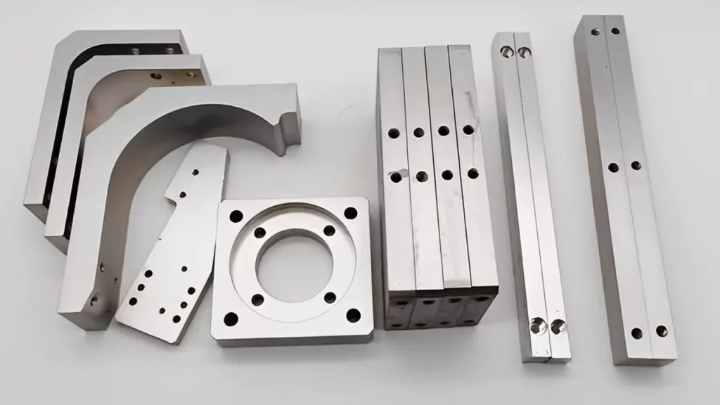
CNC milling is a highly precise and efficient manufacturing process that produces complex and accurate parts. However, despite its precision, CNC milling parts can sometimes experience deformation, resulting in defective parts that do not meet the required specifications. This deformation can occur due to various factors that affect the machining process, such as material properties, cutting parameters, machine stability, and environmental factors.
In this article, we will understand the common factors that can cause CNC milling parts deformation, the effects of this deformation on the final product, and ways to prevent it. By understanding these factors, manufacturers can take steps to ensure the production of high-quality, accurate parts that meet the desired specifications.
Factors that May Deform CNC Milling Parts:
Material and Structure:
The material and structure of the workpiece will influence the CNC milling parts’ deformation. Why is that? Because the extent of the deformation is proportional to the shape’s complexity, aspect ratio, wall thickness size, and the material’s rigidity and stability. As a result, while designing parts, the influence of these factors on workpiece deformation is minimized to the greatest extent possible.
The structure of big pieces, in particular, should be sensible. Before processing, closely control the blank, hardness, looseness, and other faults to ensure the quality of the blank and reduce the deformation of the workpiece caused by it.
Incorrect Workpiece Machining:
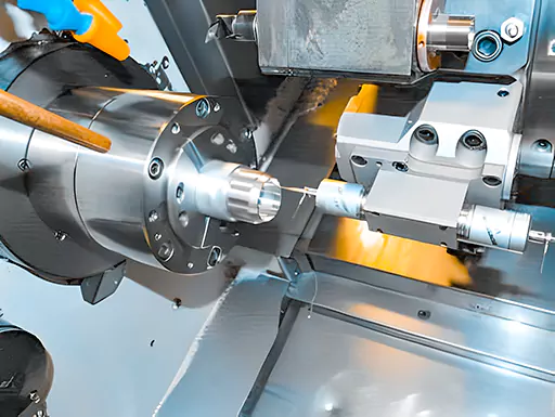
The workpiece is subjected to the cutting force during the cutting process, resulting in elastic deformation of the CNC milling parts in the direction of the force, commonly referred to as the knife phenomenon. Ensure to take corresponding measures on the tool for such deformation, which must be sharp during finishing.
On the one hand, it helps reduce the resistance formed by the friction between the tool and the workpiece; on the other hand, it can improve the tool’s heat dissipation ability when cutting the workpiece, thereby reducing the residual internal stress on the workpiece.
For example, when utilizing the single-edge milling method to mill a large plane of thin-walled parts, the tool parameters select a bigger major declination angle and a larger front angle to reduce cutting resistance. Because it cuts gently, it decreases distortion in thin-walled items and is frequently utilized in manufacturing.
A proper tool angle is critical to the amount of cutting force during turning, the thermal deformation created during turning, and the microscopic quality of the workpiece surface when turning thin-walled items. The magnitude of the tool rake angle determines the cutting deformation’s sharpness and angle.
The cutting deformation and friction of CNC milling parts are decreased because the front angle is large. Still, the front angle is too large, which reduces the wedge angle of the tool, weakens the tool strength, causes poor heat dissipation, and accelerates wear. As a result, high-speed tools are employed when turning thin-walled steel parts, the front angle is 6 ° 30 °, and the carbide tool is used to take 5 ° 20 ° at the front corner.
The tool’s back angle is large, the friction is low, and the cutting force is lowered accordingly, but the back angle is too large, and the tool’s strength is weakened. When turning thin-walled items, utilize high-speed steel turning tools with a rear angle of 6 ° 12 ° and cemented carbide tools with a back angle of 4 ° 12 °, with the larger back angle used when fine turning and the smaller back angle taken when rough turning.
The huge principal declination angle is used when the inner and outer circles of the car’s thin-walled sections are taken. You can better deal with workpiece deformation with proper tool selection is required. If you don’t want to do a low-level job, want to break free from the current quo, and want to study UG programming.
In many circumstances, high-speed cutting is used because the heat created by the friction between the tool and the workpiece deforms the workpiece. Because the chips are cut off quickly in high-speed machining, the chips absorb the majority of the cutting head, reducing the thermal deformation of the workpiece. Second, due to the decrease of the softening part of the cutting layer material in high-speed machining, the deformation of the CNC milling parts processing can also be reduced, which is beneficial to ensure the size and shape accuracy of the part.
Furthermore, cutting fluids are primarily used to reduce friction and cut temperature during cutting. Proper cutting fluid use is critical in enhancing tool durability, machining surface quality, and machining precision. As a result, a suitable amount of cutting fluid must be employed to avoid part deformation during processing.
Using an acceptable cutting quantity in machining is critical to ensuring part precision. When machining thin-walled parts with high precision requirements, symmetrical machining is commonly used to equalize the tension generated on the opposite sides to achieve a stable condition and a flat workpiece after processing. However, if a certain operation necessitates a significant amount of knife eating, the workpiece deforms due to an imbalance of tensile and compressive stress.
The clamping force when clamping the workpiece, the cutting force when cutting, the elastic deformation and plastic deformation when the workpiece hinders the tool cutting, and the temperature of the cutting zone rise, and thermal deformation occurs are all factors in the deformation of thin-walled parts during turning.
As a result, when rough machining, we must use a larger amount of back-eating knife and feed; when finishing, the knife volume is generally 0.20.5mm, the feed is generally 0.10.2mm/r or even smaller, the cutting speed is 6120m/min, and the cutting speed is as high as possible when refining. Still, it isn’t easy to be too high. Select a reasonable amount of cutting to fulfill the goal of reducing CNC milling parts deformation.
Improper Workpiece Clamping:
When clamping the workpiece, choose the appropriate clamping point and choose the appropriate clamping force based on the clamping point’s position. As a result, the clamping and support points should be as consistent as possible so that the clamping force acts on the support, the clamping point should be as close to the processing surface as feasible, and the position where the force is not easy to cause clamping deformation is chosen.
When clamping force acts in multiple directions on the workpiece, you should consider the clamping force sequence, and the clamping force should act first so that the workpiece and the support can reach the clamping force. It is not easy to be too large, and the main clamping force for balancing the cutting force should act last.
Second, either increase the contact area between the workpiece and the fixture or use an axial clamping force. Increasing the stiffness of parts is an effective technique to solve clamping deformation. However, thin-walled parts have low rigidity due to their shape and structure. Deformation will occur as a result of the clamping force’s operation.
Increasing the contact area between the workpiece and the fixture can significantly reduce workpiece distortion during clamping. When milling thin-walled parts, for example, a large number of elastic pressure plates are used to increase the force area of the contact parts; when turning the inner diameter and outer circle of the thin-walled sleeve, whether it is a simple open transition ring, an elastic mandrel, or an arc jaw, the contact area during workpiece clamping is increased.
This approach makes it easier to tolerate clamping forces and avoids part deformation. The employment of axial clamping force is also commonly utilized in production; the design and construction of special fixtures may make the clamping forces operate on the end face, which can address the workpiece’s thin wall, low stiffness, and bending CNC milling parts deformation.
Post Machining Stress Deformation:
After processing, the part has internal stress, and this internal stress distribution is relatively balanced, so the shape of the part is relatively stable. However, after removing some materials and heat treatment, the internal stress changes, and the workpiece must re-achieve the force balance, so the shape has changed.
To solve this type of CNC milling parts deformation, the workpiece that needs to be straightened can be heat treated to a certain height. Specific tooling is used to press it into a straight state. Then the tooling and the workpiece are placed in the heating furnace together, with different heating temperatures and heating times selected based on the materials of the different parts.
The internal structure of the workpiece is stable after thermal straightening. At this point, the workpiece has not only high straightness but also the hardening work phenomena is eliminated, making further finishing of the part easier. The casting should be aged to eliminate internal residual stress and reprocess following deformation, i.e., rough machining-aging-reprocessing.
Profiling processing is required for large parts, meaning that the deformation amount after the workpiece is joined is reserved in the opposite direction during processing, effectively preventing component deformation after assembly.
Conclusion:
Still, got a few questions and concerns regarding the deformation of CNC milling parts. Feel free to contact our professionals at Prototool.


