Understanding the details of mold venting in injection molding is crucial for achieving the best results in your molding processes. Proper venting not only improves part quality but also safeguards your valuable molds.
By strategically placing vents based on the specific needs of your mold and part design, you can optimize your injection molding operations for efficiency and quality. Moreover, adjusting the molding vent design according to the product requirements helps make the injection mold usage more efficient.
Don’t worry if you’re unfamiliar with any of these aspects of venting in injection molding, as this detailed article will take you through all the important considerations. So, keep reading to learn all about plastic injection mold venting.
The Importance of Proper Mold Venting
Proper venting is a critical aspect of achieving high-quality results in injection molding. It not only enhances part quality but also ensures the longevity of your molds.
This guide will take you through the essential aspects of venting injection molds, including where vents are needed, their dimensions, and the reasons behind their strategic placement.
Understanding the Need for Mold Venting
Before delving into the specifics of injection mold vents, it’s crucial to understand why this process is essential. Venting serves two primary purposes:
- Enhancing Part Quality: Proper venting ensures that air and mold gas release are effectively conducted during the injection process. This prevents air entrapment and voids, which can affect the appearance and integrity of the final product.
- Protecting Molds: Inadequate venting can lead to mold damage due to excessive pressure buildup and the corrosive nature of trapped volatiles. This can result in costly mold repairs and replacement.
Where to Implement Mold Vents?
To optimize your injection molding process, it’s important to determine where to place vents:
- Venting the Cold Well: In most cases, venting the cold well opposite the sprue is unnecessary unless you anticipate potential burn marks, which can be ground and reprocessed. Properly fitted cold-well ejector pins are usually sufficient to address any air issues.
- Venting the Runner: Adding vents to the runner depends on the runner-air-volume ratio. Short runners feeding just a few large parts often have a low ratio and don’t require venting. However, molds with long runners and multiple secondary branches can benefit from runner venting.
- Venting at the End of Fill: It’s generally advisable to vent at the end of fill. For specific part designs, such as edge-gated, dart-impact plaques, corner vents located away from the corners offer improved venting efficiency, leading to an extended vent lifespan.
- Continuous or Peripheral Venting: For fast-filling processes, consider continuous or peripheral venting. These vents run around the entire part’s outer edge, maximizing airflow area. The layout of these vents can vary depending on the part shape.
- Deep Rib Venting: Projections like deep ribs can trap air and cause issues during injection. Incorporating rib inserts can help alleviate this problem. These inserts form a split line, facilitating mold air release and avoiding potential core cracking.
The Impact of Inadequate Mold Venting
Inadequate mold vents can lead to various critical issues in injection molding, affecting both the quality of the final product and the mold itself. Insufficient venting can result in elevated mold temperatures and heightened melt pressure, resulting in the overheating of oxygen within the mold. This can trigger numerous problems, including:
Burnt Spots
Overheated oxygen can cause localized burnt spots on the molded parts, affecting their appearance and integrity.
Weak and Visible Weld Lines
Inadequate venting can lead to visible weld lines, weakening the structural integrity of the parts.
Poor Surface Finish
The excess heat generated due to poor venting can result in poor surface finishes on molded products.
Poor Mechanical Properties
Incomplete venting contributes to subpar mechanical properties in molded parts, affecting their strength and durability.
Incomplete Filling, Especially in Thin Sections
Inadequate venting can lead to incomplete filling of the mold, particularly in thin sections, resulting in incomplete or defective parts.
Irregular Dimensions
If the venting isn’t good, it can lead to changes in the size of the parts, making it hard to keep the quality of the product the same all the time.
Local Mold Cavity Corrosion
Overheating due to improper venting can lead to local corrosion of the mold cavity surface, necessitating costly repairs.

Understanding Mold Venting Methods
Plastic injection mold venting methods play a crucial role in ensuring the quality of injection-molded products. These methods are categorized into standard and non-standard processes, each serving a unique purpose in mold gas release.
1. Standard Processes
Standard venting methods are often integrated into molds or machinery by manufacturers. These include:
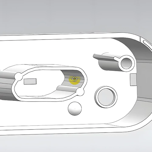
- Parting Lines: Formed where the mold halves meet, parting lines naturally release gases and can be utilized for venting.
- Vent Pins: Ejector pins with grooves along their bodies are used during ejection for air and mold gas release.
- Ejector Pins: These pins apply force to eject parts and can also vent deep features in molds, preventing gas traps.
- Tool Clearances: Used for mold venting, including parting surfaces, ejector parts, or core pulling components, while vigilance is required to prevent blockages.
- Injection Mold Sliders: These components convert vertical mold movement to horizontal motion, mitigating pressure buildup during injection.
- Mold Inserts: Core inserts are placed at melt stream convergence points to reduce pressure and gas buildup.
2. Non-Standard Processes
Manufacturers can employ non-standard techniques for mold venting, including:
- Porous Sintered Materials: Breathable steel and other porous materials facilitate gas flow but may have lower strength.
- Vacuum Technology: Vacuum devices remove air from the cavity before injection, solving air trap issues but adding cost.
- Overflow Systems: Designed to direct air away from the main part, helping increase gas penetration.
- Venting Valves: Available as external or internal valves, allowing gases to escape via channels in the mold.
- Mold Air Exhaust From Vent Groove: Vent grooves on concave molds ensure smooth exhaust and prevent overflow, which is crucial for medium and large parts.
- Active Air Vents in Injection Molding: Utilizes micro or nano-structured metal plates joined to the mold, improving venting efficiency based on surface composition.
- Mold Air Vents: Placed strategically on the mold, gate, sprue, and runners, these vents help in mold gas release as the melt progresses.
- Mandatory Mold Air Exhaust: Involves vent pins placed at gas collection points, effective but leaving marks on the final product.
Guide to Injection Molding Vent Design: 5 Key Considerations
Injection molding venting is a crucial aspect of the injection molding process, as it ensures the smooth and efficient flow of molten plastic into the mold cavity while preventing air entrapment. Proper venting is essential for producing high-quality plastic parts. In this guide, we’ll explore the standards and design considerations for injection molding vents.
1. Vent Land Dimensions
Vent land refers to the space between the mold cavity and the mold surface. The standard vent land width is 0.06 inches. However, the vent clearance can vary from 0.12 to 0.50 inches in width and should be 0.02 inches deep.
These dimensions are essential for effective venting. Vents are typically ground, but milled vents must be polished to ensure a smooth finish.
2. Perimeter Vent Land
Perimeter vent land surrounds the mold cavity and should have a minimum width of 0.125 inches and a maximum width of 0.250 inches. Proper perimeter venting helps to release air trapped within the cavity during the injection process.
3. Vent Placement
Effective venting is achieved by placing vents directly opposite the gate and at all runner ends and cold well slugs. This strategic positioning ensures that air can escape from the mold cavity as plastic material flows in.
4. Ejector Pin Vents
In some cases, ejector pin vents may be necessary to allow air to escape.
5. Common Vent Depths (in inches)
Different plastic materials require varying vent depths to ensure proper venting and prevent air entrapment. For a quick reference of the common vent depths for various plastics, you can refer to the table below:
| Plastic Material | Vent Depth Range (in inches) |
| ABS | 0.001 – 0.0015 |
| Acetal | 0.0005 – 0.001 |
| Acrylic | 0.0015 – 0.002 |
| Cellulose Acetate (CAB) | 0.001 – 0.0015 |
| Ethylene Vinyl Acetate | 0.001 – 0.0015 |
| Ionomer | 0.0005 – 0.001 |
| LCP | 0.0005 – 0.0007 |
| Nylon | 0.0003 – 0.0005 |
| PPO/PPS (Noryl) | 0.001 – 0.002 |
| Polycarbonate | 0.0015 – 0.0025 |
| PET, PBT, Polyesters | 0.0005 – 0.0007 |
| Polysulfone | 0.001 – 0.002 |
| Polyethylene | 0.0005 – 0.0012 |
| Polypropylene | 0.0005 – 0.0012 |
| Polystyrene | 0.0007 – 0.0012 |
| High Impact Polystyrene | 0.0008 – 0.0012 |
| PVC (Rigid) | 0.0006 – 0.001 |
| PVC (Flexible) | 0.0005 – 0.0007 |
| Polyurethane | 0.0004 – 0.0008 |
| SAN | 0.001 – 0.0015 |
| T/P Elastomer | 0.0005 – 0.0007 |
Conclusion
Ultimately, understanding the ‘where and how’ of venting is crucial in injection molding to ensure top-quality products. It prevents defects and maintains part integrity.
Whether using standard methods like parting lines or innovative approaches such as porous materials, achieving excellence is the goal. For precision and expertise in injection molding, turn to Prototool.
As a professional CNC manufacturing and plastic injection molding service provider, we excel in addressing advanced and custom product manufacturing needs, including meticulous attention to injection mold venting.
So, with Prototool, you’re assured of industry-leading results. Master these techniques and make informed decisions for outstanding injection molding outcomes.

