CNC milling is the common machining process that is performed under computer control. Milling is cutting a substance with a revolving tool, such as wood, metal, or plastic. The controls in CNC milling govern everything from each cutter’s tool sequence and toolpath to the spindle RPM and feed rate. There are various varieties of CNC milling machining, each with a distinct amount of intricacy in the cutting process. The most fundamental machines have three axes of motion. Milling machines with five or more axes of motion control are more sophisticated. These machines are used to create increasingly complicated parts.
If you’re unfamiliar with using a milling machine, this guide will cover all about its components, processing methods, and everything you need to know about the milling process.
CNC Milling Techniques:
Milling can be used for a variety of purposes, including the manufacture of parts. The first sort of milling was plain milling or cutting flat surfaces parallel to the revolving axis of the cutting tool. The introduction of CNC machining has resulted in the development of various types of milling, including:
- Face Milling: Cutting material to form a surface perpendicular to the cutter’s rotating axis.
- Form Milling: Cutting material creates uneven surfaces such as curves.
- Gang milling: Removing material with two or more cutters simultaneously to increase production.
- Angular Milling: Removing material from a workpiece’s flat surface at an angle.
Milling Machining Components:
Ø Base:
The base is the foundation of a machine to which all other parts are attached. Because the base bears the entire load, it must have high compressive strength and is made of cast iron.
Ø Column:
A vertically mounted column on the base. It supports the knee, table, and other driving members, as well as a home for all the other driving members. The column is a hollow member that houses the spindle and table’s driving gears and, on occasion, a motor.
Ø Knee:
A casting that holds the saddle and table in place. The entire gearing mechanism is contained within the knee. Dovetail ways secure it to the column. A vertical positioning screw supports and adjusts the knee (elevating screw). The elevating screw raises and lowers the knee by raising or lowering the lever with a hand or power feed.
Ø Saddle:
It is placed between the table and the knee, serving as an intermediary. This is capable of moving transversally to the column face. This slides over the provided guideways on the knee, which are perpendicular to the column face. Speaking of which, the primary function is to provide horizontal motion to the workpiece. This is also made of cast iron.
Ø Table:
This is a rectangular casting on the top of the saddle designed over the knee. Moreover, it is the part of a machine that holds the workpiece while machining. It’s made of cast iron and has a T-slot carved into it. Vertical motion is provided by moving the knee up and down. The feed screw generates horizontal motion. Moving the saddle creates a horizontal (transverse) motion.
Ø Overhanging Arm:
The overhanging arm is used to secure arbor support. It could be made up of one or two cylindrical bars that move through the column’s perforations. It is constructed of cast iron.
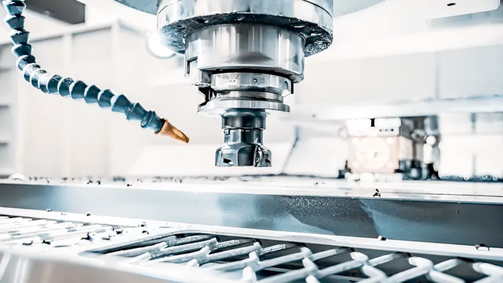
Ø Spindle:
A spindle is the fundamental component of the machine that holds the tool in place. This spindle drives arbors, cutters, and attachments on a machine.
Ø Arbor:
This mechanical component serves as an extension of the spindle in a horizontal mill machine. It is installed on the spindle as needed. This holds the instrument in place and moves it in the right direction.
Ø Supports for Arbors:
Arbor supports in mill machines are mainly of two types. The first has a small diameter bearing hole, usually up to 1 inch in diameter, and the second has a big diameter bearing hole, usually up to 23/4 inch in diameter. An oil reservoir in the arbor support lubricates the bearing surfaces. It is clampable anyplace on the overarm. The arbor support is only seen on horizontal milling machines.
Ø Head for Milling:
It’s the top of a vertical milling machine. It comprises a spindle, a drive motor, and other control devices.
Ø Ram:
The arm is attached to the column at one end and the milling head at the other. A hand lever allows the ram to be moved transversally, both inwards and outwards, on the column.
What are the Steps in the CNC Milling Machining Process?
Several actions must be done to move from the CAD model to the real part. The CNC milling method is detailed in detail below.
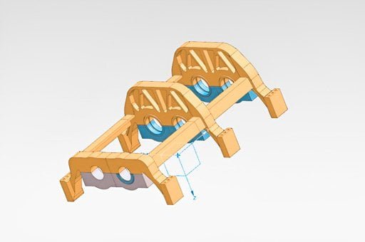
· Create a CAD Model
The CNC milling machining process begins with creating a 3D CAD model of the object to be manufactured. This CAD model will include information about the part’s dimensions, geometry, and shape. Designers must create CAD models that CNC milling machining can cut. Undercuts should be avoided (or kept to a minimum) while designing parts. The specific CNC machine’s capability determines the machined undercut’s size. Undercuts are characteristics in a recessed or sunken part that cannot be cut using normal tools. While CNC mills may cut undercuts, they usually require specialized tools, multi-axis milling machines, or both, which results in higher tooling and manufacturing costs.
· CAD to CNC Conversion
Once a proper 3D CAD model for a certain part has been built, a CNC program must be written to manage its manufacture on the CNC milling machining. The designer can use CAM software to write program instructions for the CNC machine to direct the movement of the tools and cutters during manufacturing.
G-code or M-code is frequently used to write these applications. G-code sections of the software concentrate on tool operating characteristics such as spindle speed, movement direction, and cut depth. M-code instructions are used for various operations, such as tool changes, machine power on and off, and other auxiliary duties. A simulator is frequently included in CAM software, allowing users to test if their CNC programs can effectively build the intended part.
· Setting up a CNC Milling Machine
The CNC milling machine is ready to produce the planned part after completing the CAD model and CNC program. A machine operator will load the CNC program into the milling machine and insert a pre-prepared blank with the necessary pre-machining dimensions into the machine’s work-holding mechanism. The machine is also outfitted with the necessary tools, spindles, vices, and fittings.
· Program Implementation
The machining program can be executed after the CAD model has been made, the CNC program has been created, and the CNC milling machining has been readied. Human intervention is rarely required when a CNC program is running. Line by line, the CNC milling machine will execute all specified machining operations on the workpiece. After the entire program has been completed, the part can proceed to the next planned manufacturing step.
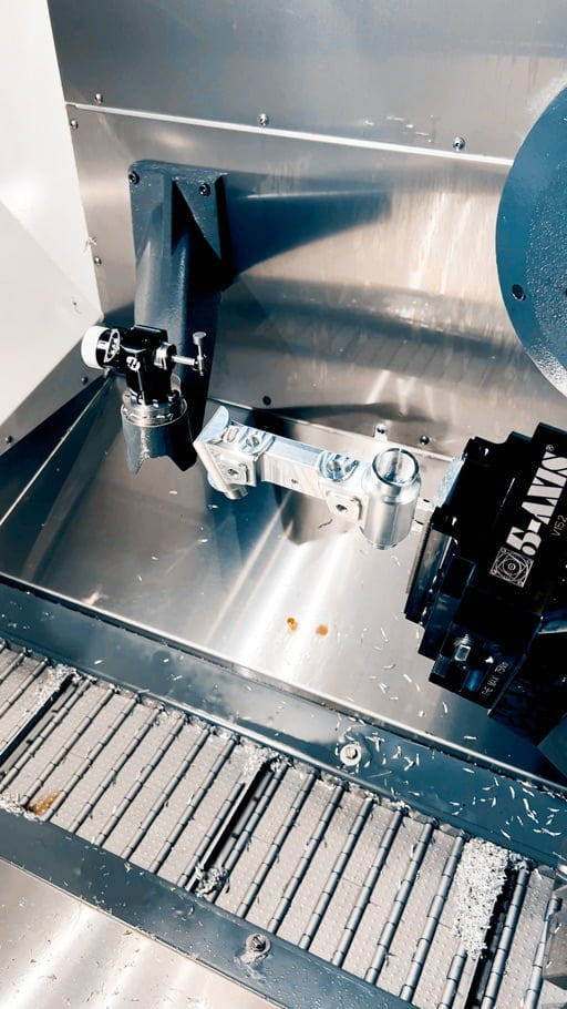
The Following Machines Are Used in the CNC Milling Process:
Several pieces of equipment must be combined to achieve a successful CNC milling operation. The following items are frequently required for CNC milling:
Worktable: The worktable keeps the workpiece in position while machining.
Saddle: The saddle is found beneath the work table. It provides additional support and guides the movement of the worktable parallel to the tool’s rotational axis.
Knee: It is placed beneath the saddle and aids in support of both the saddle and the worktable. Its vertical position can be changed to accommodate varying item thicknesses.
Spindle: The spindle holds the cutting tool and directs its translational and rotational movement.
Arbor: An arbor is a shaft connected to the spindle. The arbor is equipped with tools.
Ram: A ram is a piece of optional equipment that is typically utilized in vertical milling or angular milling machines. It serves to sustain the spindle.
Machine Equipment: CNC milling requires cutting tools such as end mills and other tools.
Interface: The interface allows the operator to communicate with the CNC machine’s computer. At the very least, this will include a keyboard and a display screen.
Conclusion:
This article introduced CNC milling machining, defined it, and examined how it operates and the various methods. Please contact Prototool if you want to learn more about CNC milling.


