When it comes to drafting engineering diagrams for plastic components, many engineers face a common dilemma: how to set the right dimensional tolerances. Imagine a scenario where you have a dimension of 100mm in length. The question arises: should the tolerance be set at +/-0.1mm, +/-0.2mm, +/-0.3mm, +/-0.4mm, or perhaps +/-0.5mm?
If the tolerances are too stringent, suppliers might find them challenging to achieve, subsequently driving up costs. On the other hand, if they are too lenient, there is a potential risk that the final assembly could jeopardize the product’s aesthetics, functionality, and overall reliability.
Striking the right balance in tolerance settings is paramount. Being overly precise or too lenient can lead to the perception of lacking expertise in the intricacies of injection molding. But is there a go-to standard or a handy table that engineers can turn to for guidance?
In this article, we will explore four prominent standards for injection molding tolerances of plastic parts. Additionally, we will provide insightful recommendations to help you navigate this intricate terrain.
Factors Influencing Tolerances in Plastic Components
Before diving into the standards, it’s essential to understand from the perspective of the injection molding process what factors play a role in determining the tolerances of plastic components. Several elements come into play when considering the dimensional allowances of molded parts. These include the characteristics of the plastic material, product design, mold design, and the intricacies of the injection molding process itself.
| Plastic Properties | Product Design | Mold Design | Injection Molding Process |
| Shrinkage Rate (Isotropic and Anisotropic) | Product Structure | Mold Precision | Injection Molding Machine Performance |
| Dimensional Stability | Wall Thickness | Number of Mold Cavities | Injection Pressure/Speed |
| Viscosity | Draft Angle | Runner System | Holding Pressure/Speed |
| Addition of Reinforcing Fibers | Symmetry | Ejection System | Melting Temperature and Mold Temperature |
| Surface Treatment | Cooling System | Clamping Force | |
| Dimension Size | Mold Design/Layout | Repetitive Production Capability |
From the myriad factors listed in the table, two stand out as particularly pivotal:

1. Shrinkage Rate of Plastic Material:
The shrinkage rate of the plastic material is a significant determinant of dimensional accuracy. Materials with a lower shrinkage rate tend to yield higher dimensional precision. Conversely, those with a higher shrinkage rate often result in reduced accuracy.
2. Influence of Mold Movement on Dimensions:
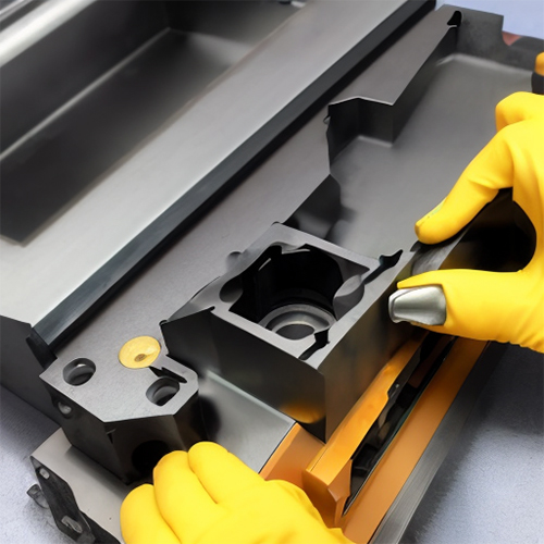
The position of the dimension within the mold can also affect its accuracy. If a dimension is entirely within a single mold cavity, it remains unaffected by mold movements, leading to higher precision. However, if a dimension spans across two mold cavities (or is associated with an angled sliding block), there’s an added assembly error due to the two cavities (or the sliding block). This, combined with the interplay between the moving parts, can lead to a decrease in dimensional accuracy.
Four Recognized Standards for Plastic Component Tolerances
When setting dimensional allowances for plastic components, the industry widely recognizes several standards. These standards provide guidelines that help engineers and manufacturers ensure the quality and functionality of their products. Here’s a closer look at four of these standards:
1. Chinese National Standard: GB/T 14486-2008
| 0 | 3 | 6 | 10 | 14 | 18 | 24 | 30 | 40 | 50 | 65 | 80 | 100 | 120 | 140 | 160 | 180 | 200 | 225 | 250 | ||
| MT1 | A | 0.1 | 0.08 | 0.09 | 0.1 | 0.11 | 0.12 | 0.14 | 0.16 | 0.18 | 0.2 | 0.23 | 0.26 | 0.29 | 0.32 | 0.36 | 0.4 | 0.44 | 0.48 | 0.52 | |
| B | 0.1 | 0.16 | 0.18 | 0.2 | 0.21 | 0.22 | 0.24 | 0.26 | 0.28 | 0.3 | 0.33 | 0.36 | 0.39 | 0.42 | 0.46 | 0.5 | 0.54 | 0.58 | 0.62 | ||
| MT2 | A | 0.1 | 0.12 | 0.14 | 0.16 | 0.18 | 0.2 | 0.22 | 0.24 | 0.26 | 0.3 | 0.34 | 0.38 | 0.42 | 0.46 | 0.5 | 0.54 | 0.6 | 0.66 | 0.72 | |
| B | 0.2 | 0.22 | 0.24 | 0.26 | 0.28 | 0.3 | 0.32 | 0.34 | 0.36 | 0.4 | 0.44 | 0.48 | 0.52 | 0.56 | 0.6 | 0.64 | 0.7 | 0.76 | 0.82 | ||
| MT3 | A | 0.1 | 0.14 | 0.16 | 0.18 | 0.2 | 0.22 | 0.26 | 0.3 | 0.34 | 0.4 | 0.46 | 0.52 | 0.58 | 0.64 | 0.7 | 0.78 | 0.86 | 0.92 | 1 | |
| B | 0.3 | 0.34 | 0.36 | 0.38 | 0.4 | 0.42 | 0.46 | 0.5 | 0.54 | 0.6 | 0.66 | 0.72 | 0.78 | 0.84 | 0.9 | 0.98 | 1.06 | 1.12 | 1.2 | ||
| MT4 | A | 0.2 | 0.18 | 0.2 | 0.24 | 0.28 | 0.32 | 0.36 | 0.42 | 0.48 | 0.56 | 0.64 | 0.72 | 0.82 | 0.92 | 1.02 | 1.12 | 1.24 | 1.36 | 1.48 | |
| B | 0.4 | 0.38 | 0.4 | 0.44 | 0.48 | 0.52 | 0.56 | 0.62 | 0.68 | 0.76 | 0.84 | 0.92 | 1.02 | 1.12 | 1.22 | 1.32 | 1.44 | 1.56 | 1.68 | ||
| MT5 | A | 0.2 | 0.24 | 0.28 | 0.32 | 0.38 | 0.44 | 0.5 | 0.56 | 0.64 | 0.74 | 0.86 | 1 | 1.14 | 1.28 | 1.44 | 1.6 | 1.76 | 1.92 | 2.1 | |
| 。B | 0.4 | 0.44 | 0.48 | 0.52 | 0.58 | 0.64 | 0.7 | 0.76 | 0.84 | 0.94 | 1.06 | 1.2 | 1.34 | 1.48 | 1.64 | 1.8 | 1.96 | 2.12 | 2.3 | ||
| MT6 | A | 0.3 | 0.32 | 0.38 | 0.46 | 0.52 | 0.6 | 0.7 | 0.8 | 0.94 | 1.1 | 1.28 | 1.48 | 1.72 | 2 | 2.2 | 2.4 | 2.6 | 2.9 | 3.2 | |
| B | 0.5 | 0.52 | 0.58 | 0.66 | 0.72 | 0.8 | 0.9 | 1 | 1.14 | 1.3 | 1.48 | 1.68 | 1.92 | 2.2 | 2.4 | 2.6 | 2.8 | 3.1 | 3.4 | ||
| A | 0.4 | 0.46 | 0.56 | 0.66 | 0.76 | 0.86 | 0.98 | 1.12 | 1.32 | 1.54 | 1.8 | 2.1 | 2.4 | 2.7 | 3 | 3.3 | 3.7 | 4.1 | 4.5 | ||
| B | 0.6 | 0.66 | 0.76 | 0.86 | 0.96 | 1.06 | 1.18 | 1.32 | 1.52 | 1.74 | 2 | 2.3 | 2.6 | 2.9 | 3.2 | 3.5 | 3.9 | 4.3 | 4.7 | ||
In this standard, ‘A‘ represents the dimensional tolerance values unaffected by mold movements, while ‘B‘ denotes those influenced by mold movements. The MT1 level is considered a precision grade, only achievable when stringent process control measures are employed, coupled with high-precision molds, equipment, and raw materials.
We determine tolerance levels based on the shrinkage rate of the plastic material:
| Shrinkage Characteristic Value Sv/% | Tolerance Level | ||
| Specified Tolerance Dimension | Unspecified Tolerance Dimension | ||
| High Precision | General Precision | ||
| >0~1 | MT2 | MT3 | MT5 |
| >1~2 | MT3 | MT4 | MT6 |
| >2~3 | MT4 | MT5 | MT71MT7 |
| >3 | MT5 | MT6 | |
a. Materials with 0~1% shrinkage include ABS, PC, PC/ABS, PA with fiberglass filler, and PP with filler.
b. Materials with 1~2% shrinkage include PA and POM with dimensions ≤150mm.
c. Materials with 2~3% shrinkage include PP, POM with dimensions >150mm, and PE.
d. Materials with >3% shrinkage typically include soft PVC.
2. Automotive Industry Standard: QC-T-29017-1991
This standard addresses the maximum deviation in dimensional tolerances for molded plastic parts in the automotive sector.
| 0 | 3 | 6 | 10 | 15 | 22 | 30 | 40 | 53 | 70 | 90 | 120 | 160 | 200 | 250 | 315 | 400 | 500 | 630 | 800 | 800+ | ||
| 0-1 | a | 0.09 | 0.1 | 0.11 | 0.13 | 0.15 | 0.17 | 0.2 | 0.24 | 0.28 | 0.34 | 0.41 | 0.5 | 0.6 | 0.8 | 1 | 1.2 | 1.5 | 1.9 | 2.4 | 2.9 | |
| b | 0.19 | 0.2 | 0.21 | 0.23 | 0.25 | 0.27 | 0.3 | 0.34 | 0.38 | 0.44 | 0.51 | 0.6 | 0.7 | 0.9 | 1.1 | 1.3 | 1.6 | 2 | 2.5 | 3 | ||
| 1一2 | a | 0.11 | 0.12 | 0.14 | 0.17 | 0.2 | 0.24 | 0.28 | 0.33 | 0.4 | 0.5 | 0.6 | 0.75 | 0.95 | 1.15 | 1.45 | 1.8 | 2.2 | 2.8 | 3.5 | 4.5 | |
| b | 0.21 | 0.22 | 0.24 | 0.27 | 0.3 | 0.34 | 0.38 | 0.43 | 0.5 | 0.6 | 0.7 | 0.85 | 1.05 | 1.25 | 1.55 | 1.9 | 2.3 | 2.9 | 3.6 | 4.6 | ||
| 2一3 | a | 0.15 | 0.17 | 0.2 | 0.24 | 0.28 | 0.33 | 0.39 | 0.47 | 0.58 | 0.71 | 0.87 | 1.1 | 1.4 | 1.7 | 2.1 | 2.7 | 3.3 | 4.2 | 5.2 | 6.5 | |
| b | 0.25 | 0.27 | 0.3 | 0.34 | 0.38 | 0.43 | 0.49 | 0.57 | 0.68 | 0.81 | 0.97 | 1.2 | 1.5 | 1.8 | 2.2 | 2.8 | 3.4 | 4.3 | 5.3 | 6.6 | ||
| 3一4 | a | 0.2 | 0.23 | 0.27 | 0.32 | 0. 39 | 0.47 | 0.56 | 0.68 | 0.84 | 1.05 | 1.3 | 1.7 | 2.1 | 2.6 | 3.2 | 4 | 5 | 6.2 | 7.8 | 9.9 | |
| b | 0.3 | 0.33 | 0.37 | 0.42 | 0.49 | 0.57 | 0.66 | 0.78 | 0.94 | 1.15 | 1.4 | 1.8 | 2.2 | 2.7 | 3.3 | 4.1 | 5.1 | 6.3 | 7.9 | 10 | ||
Here, ‘a‘ represents dimensional tolerance values unaffected by mold movements, while ‘b‘ denotes those influenced by mold movements.
| Shrinkage% | Shrinkage Characteristic Value and Its Classification | Common Materials |
| 0~1 | 0-1 | ABS、 PA、 PC、 PS |
| 1~2 | 1-2 | PA6, PA66, PO (less than 150mm), PP (filled) |
| 2~3 | 2-3 | PE, PP, POM (greater than 150mm) |
| 3~4 | 3-4 |
3. Volkswagen Standard: DIN16901-1982
| 0 | 1 | 3 | 6 | 10 | 15 | 22 | 30 | 40 | 53 | 70 | 90 | 120 | 160 | 200 | 250 | 315 | 400 | 500 | 630 | 800 | 1000 | ||
| General Injection Molding Tolerances | |||||||||||||||||||||||
| 160 | A | 0.28 | 0.3 | 0.33 | 0.37 | 0.4 | 0.5 | 0.57 | 0.66 | 0.78 | 0.94 | 1.2 | 1.4 | 1.8 | 2.2 | 2.7 | 3.3 | 4.1 | 5.1 | 6.3 | 7.9 | 10 | |
| B | 0.18 | 0.2 | 0.23 | 0.27 | 0.3 | 0.4 | 0.47 | 0.56 | 0.68 | 0.84 | 1.1 | 1.3 | 1.7 | 2.1 | 2.6 | 3.2 | 4 | 5 | 6.2 | 7.8 | 9.9 | ||
| 150 | A | 0.23 | 0.3 | 0.27 | 0.3 | 0.3 | 0.4 | 0.43 | 0.49 | 0.57 | 0.68 | 0.8 | 0.97 | 1.2 | 1.5 | 1.8 | 2.2 | 2.8 | 3.4 | 4.3 | 5.3 | 6.6 | |
| B | 0.13 | 0.2 | 0.17 | 0.2 | 0.2 | 0.3 | 0.33 | 0.39 | 0.47 | 0.58 | 0.7 | 0.87 | 1.1 | 1.4 | 1.7 | 2.1 | 2.7 | 3.3 | 4.2 | 5.2 | 6.5 | ||
| 140 | A | 0.2 | 0.2 | 0.22 | 0.24 | 0.3 | 0.3 | 0.34 | 0.38 | 0.43 | 0.5 | 0.6 | 0.7 | 0.85 | 1.05 | 1.25 | 1.55 | 1.9 | 2.3 | 2.9 | 3.6 | 4.5 | |
| B | 0.1 | 0.1 | 0.12 | 0.14 | 0.2 | 0.2 | 0.24 | 0.28 | 0.33 | 0.4 | 0.5 | 0.6 | 0.75 | 0.95 | 1.15 | 1.45 | 1.8 | 2.2 | 2.8 | 3.5 | 4.4 | ||
| 130 | A | 0.18 | 0.2 | 0.2 | 0.21 | 0.2 | 0.3 | 0.27 | 0.3 | 0.34 | 0.38 | 0.4 | 0.51 | 0.6 | 0.7 | 0.9 | 1.1 | 1.3 | 1.6 | 2 | 2.5 | 3 | |
| B | 0.08 | 0.1 | 0.1 | 0.11 | 0.1 | 0.2 | 0.17 | 0.2 | 0.24 | 0.28 | 0.3 | 0.41 | 0.5 | 0.6 | 0.8 | 1 | 1.2 | 1.5 | 1.9 | 2.4 | 2.9 | ||
| Specified Dimension Tolerances | |||||||||||||||||||||||
| 160 | A | 0.56 | 0.6 | 0.66 | 0.74 | 0.8 | 1 | 1.14 | 1.32 | 1.56 | 1.88 | 2.3 | 2.8 | 3.6 | 4.4 | 5.4 | 6.6 | 8.2 | 10.2 | 12.5 | 15.8 | 20 | |
| B | 0.36 | 0.4 | 0.46 | 0.54 | 0.6 | 0.8 | 0.94 | 1.12 | 1.36 | 1.68 | 2.1 | 2.6 | 3.4 | 4.2 | 5.2 | 6.4 | 8 | 10 | 12.3 | 15.6 | 19.8 | ||
| 1450 | A | 0.46 | 0.5 | 0.54 | 0.6 | 0.7 | 0.8 | 0.86 | 0.98 | 1.14 | 1.36 | 1.6 | 1.94 | 2.4 | 3 | 3.6 | 4.4 | 5.6 | 6.8 | 8.6 | 10.6 | 13.2 | |
| B | 0.26 | 0.3 | 0.34 | 0.4 | 0.5 | 0.6 | 0.66 | 0.78 | 0.94 | 1.16 | 1.4 | 1.74 | 2.2 | 2.8 | 3.4 | 4.2 | 5.4 | 6.6 | 8.4 | 10.4 | 13 | ||
| 140 | A | 0.4 | 0.4 | 0.44 | 0.48 | 0.5 | 0.6 | 0.68 | 0.76 | 0.86 | 1 | 1.2 | 1.4 | 1.7 | 2.1 | 2.5 | 3.1 | 3.8 | 4.6 | 5.8 | 7.2 | 9 | |
| B | 0.2 | 0.2 | 0.24 | 0.28 | 0.3 | 0.4 | 0.48 | 0.56 | 0.66 | 0.8 | 1 | 1.2 | 1.5 | 1.9 | 2.3 | 2.9 | 3.6 | 4.4 | 5.6 | 7 | 8.8 | ||
| 130 | A | 0.36 | 0.4 | 0.4 | 0.42 | 0.5 | 0.5 | 0.54 | 0.6 | 0.68 | 0.76 | 0.9 | 1.02 | 1.2 | 1.5 | 1.8 | 2.2 | 2.6 | 3.2 | 3.9 | 4.9 | 6 | |
| B | 0.16 | 0.2 | 0.2 | 0.22 | 0.3 | 0.3 | 0.34 | 0.4 | 0.48 | 0.56 | 0.7 | 0.82 | 1 | 1.3 | 1.6 | 2 | 2.4 | 3 | 3.7 | 4.7 | 5.8 | ||
| 120 | A | 0.32 | 0.3 | 0.36 | 0.38 | 0.4 | 0.4 | 0.46 | 0.5 | 0.54 | 0.6 | 0.7 | 0.78 | 0.9 | 1.06 | 1.24 | 1.5 | 1.8 | 2.2 | 2.6 | 3.2 | 4 | |
| B | 0.12 | 0.1 | 0.16 | 0.18 | 0.2 | 0.2 | 0.26 | 0.3 | 0.34 | 0.4 | 0.5 | 0.58 | 0.7 | 0.86 | 1.04 | 1.3 | 1.6 | 2 | 2.4 | 3 | 3.8 | ||
| 110 | A | 0.18 | 0.2 | 0.22 | 0.24 | 0.3 | 0.3 | 0.3 | 0.32 | 0.36 | 0.4 | 0.4 | 0.5 | 0.58 | 0.68 | 0.8 | 0.96 | 1.16 | 1.4 | 1.7 | 2.1 | 2.6 | |
| B | 0.08 | 0.1 | 0.12 | 0.14 | 0.2 | 0.2 | 0.2 | 0.22 | 0.26 | 0.3 | 0.3 | 0.4 | 0.48 | 0.58 | 0.7 | 0.86 | 1.06 | 1.3 | 1.6 | 2 | 2.5 | ||
| Precison | A | 0.1 | 0.1 | 0.14 | 0.16 | 0.2 | 0.2 | 0.24 | 0.26 | 0.28 | 0.31 | 0.4 | 0.4 | 0.5 | |||||||||
| B | 0.05 | 0.1 | 0.07 | 0.08 | 0.1 | 0.1 | 0.14 | 0.16 | 0.18 | 0.21 | 0.3 | 0.3 | 0.4 | ||||||||||
The numbers 110, 120, 130, 140, and 150 in this standard refer to the different tolerance grades.
| Materials | General Tolerances | Specified Tolerance Dimension | |
| Series 1 | Series 2 | ||
| PE、 PON (<150mm)、PP | 150 | 140 | 130 |
| PA6、PA66、POM (≥150mm)、PP(filled)、PP+EPDM | 140 | 130 | 120 |
| ABS、PA、PC、PS、PVC(Without plasticizers) | 130 | 120 | |
4. SAIC Group Standard: MGR ES.22.PL.103
| 0 | 1 | 3 | 6 | 10 | 15 | 22 | 30 | 40 | 55 | 70 | 90 | 120 | 160 | 200 | 250 | 315 | 400 | 500 | 650 | 800 | 1000 | 1200 | 1400 | 1600 | 1800 | 2000 | ||
| Group One | Precision | 0.05 | 0.06 | 0.07 | 0.08 | 0.08 | 0.09 | 0.11 | 0.13 | 0.14 | 0.17 | 0.2 | 0.25 | 0.3 | 0.36 | 0.44 | 0.5 | 0.7 | 0.9 | 1.2 | 1.5 | 1.9 | 2.3 | 2.65 | 3.05 | 3.4 | 3.8 | |
| General | 0.07 | 0.08 | 0.09 | 0.09 | 0.11 | 0.13 | 0.14 | 0.17 | 0.2 | 0.24 | 0.29 | 0.35 | 0.43 | 0.51 | 0.68 | 0.85 | 1.08 | 1.38 | 1.83 | 2.3 | 2.9 | 3.5 | 4.05 | 4.65 | 5.2 | 5.8 | ||
| Group Two | Precision | 0.06 | 0.07 | 0.08 | 0.08 | 0.1 | 0.11 | 0.13 | 0.15 | 0.18 | 0.21 | 0.26 | 0.31 | 0.38 | 0.45 | 0.6 | 0.75 | 0.98 | 1.28 | 1.73 | 2.2 | 2.8 | 3.35 | 3.9 | 4.5 | 5.05 | 5.6 | |
| General | 0.08 | 0.09 | 0.1 | 0.12 | 0.14 | 0.17 | 0.2 | 0.23 | 0.27 | 0.33 | 0.41 | 0.5 | 0.62 | 0.79 | 0.95 | 1.2 | 1.63 | 2.13 | 2.88 | 3.6 | 4.63 | 5.55 | 6.5 | 7.4 | 8.3 | 9.25 | ||
| Group Three | Precision | 0.07 | 0.08 | 0.08 | 0.1 | 0.12 | 0.14 | 0.17 | 0.19 | 0.23 | 0.28 | 0.34 | 0.41 | 0.52 | 0.65 | 0.08 | 1 | 1.35 | 1.75 | 2.35 | 3 | 3.75 | 4.5 | 5.25 | 6 | 6.75 | 7.5 | |
| General | 0.1 | 0.11 | 0.12 | 0.14 | 0.17 | 0.2 | 0.24 | 0.28 | 0.34 | 0.41 | 0.51 | 0.62 | 0.79 | 1 | 1.2 | 1.5 | 2.05 | 2.65 | 3.55 | 4.5 | 5.65 | 6.8 | 7.9 | 9.05 | 10.15 | 11.3 | ||
The first group of plastic materials includes ABS, fiberglass-filled ABS, filled PA6, filled PA66, filled PA11, filled PA12, PC, fiberglass-filled PC, and PC/ABS. The second group comprises PA6, PA66, PA11, PA12, fiberglass-filled PP, PS, and rigid PVC. The third group includes PE, PP, PS, and soft PVC.
By understanding and adhering to these standards, manufacturers can ensure that their plastic components meet the necessary dimensional allowances, resulting in products that are both functional and aesthetically pleasing.
Recommended Tolerance Standards for Plastic Components
When we compare the four aforementioned standards, particularly by focusing on specific data points, we can make several observations:
- The SAIC Motor standard has the highest requirements.
- The automotive industry standard and the general standard (DIN16901-1982) have roughly similar requirements, with the latter being slightly more lenient.
- The Chinese National Standard (GB/T 14486-2008) has the most relaxed requirements. For instance, the tolerance for ABS plastic with a dimension of 100mm is +/-0.26mm. Considering the current capabilities of injection molding processes, we deem this standard’s requirements as too lenient and do not recommend their usage.
| Materials Dimension | GB/T 14486-2008 | Automotive Industry Standard: QC-T- | SAIC Group Standard: MGR ES.22.PL.103 | Volkswagen Standard: DIN16901-1982 | ||||||||||||
| Specified Dimension Tolerances | Unspecified Dimension Tolerances | General | Specified Dimension Tolerances | |||||||||||||
| High Precision | General | Series 01 | Series 02 | |||||||||||||
| MT2 | MT3 | MT5 | 0-1 | Group One | 130 | 120 | 110 | |||||||||
| A | B | A | B | A | B | A | B | Precision | General | A | B | A | B | A | B | |
| 5 | 0.12 | 0.22 | 0.1 | 0.3 | 0.2 | 0.22 | 0.1 | 0.2 | 0.07 | 0.09 | 0.2 | 0.1 | 0.36 | 0.16 | 0.22 | 0.12 |
| 20 | 0.2 | 0.3 | 0.2 | 0.4 | 0.22 | 0.32 | 0.15 | 0.25 | 0.09 | 0.13 | 0.25 | 0.15 | 0.42 | 0.22 | 0.28 | 0.18 |
| 100 | 0.38 | 0.48 | 0.5 | 0.7 | 0.5 | 0.6 | 0.41 | 0.51 | 0.25 | 0.35 | 0.51 | 0.41 | 0.78 | 0.58 | 0.5 | 0.4 |
| 200 | 0.6 | 0.7 | 0.9 | 1.1 | 0.88 | 0.98 | 0.6 | 0.7 | 0.36 | 0.51 | 0.7 | 0.6 | 1.06 | 0.86 | 0.68 | 0.58 |
| PA(unfilled), POM(<150mm) | MT3 | MT4 | MT6 | 1-2 | Group Two | 140 | 130 | 120 | ||||||||
| A | B | A | B | A | B | A | B | Precision | General | A | B | A | B | A | B | |
| 5 | 0.14 | 0.34 | 0.2 | 0.4 | 0.16 | 0.26 | 0.1 | 0.2 | 0.08 0.1 | 0.22 | 0.12 | 0.4 | 0.2 | 0.4 | 0.2 | |
| 20 | 0.22 | 0.42 | 0.3 | 0.5 | 0.3 | 0.4 | 0.2 | 0.3 | 0.11 0.17 | 0.3 | 0.2 | 0.5 | 0.3 | 0.4 | 0.2 | |
| 100 | 0.52 | 0.72 | 0.7 | 0.9 | 0.74 | 0.84 | 0.6 | 0.7 | 0.31 0.5 | 0.7 | 0.6 | 1.02 | 0.82 | 0.8 | 0.6 | |
| 200 | 0.86 | 1.06 | 1.2 | 1.4 | 1.3 | 1.4 | 1 | 1.1 | 0.45 0.79 | 1.05 | 0.95 | 1.5 | 1.3 | 1.1 | 0.9 | |
| PP、PE、POM(≥150mm) | MT4 | MT5 | MT7 | 2-3 | Group Three | 150 | 140 | 130 | ||||||||
| A | B | A | B | A | B | A | B | Precision | General | A | B | A | B | A | B | |
| 5 | 0.18 | 0.38 | 0.2 | 0.4 | 0.23 | 0.33 | 0.2 | 0.27 | 0.08 | 0.12 | 0.27 | 0.2 | 0.44 | 0.2 | 0.4 | 0.2 |
| 20 | 0.32 | 0.52 | 0.44 | 0.64 | 0.43 | 0.53 | 0.3 | 0.4 | 0.14 | 0.2 | 0.38 | 0.28 | 0.6 | 0.4 | 0.5 | 0.3 |
| 100 | 0.72 | 0.92 | 1 | 1.2 | 1.05 | 1.15 | 0.9 | 1 | 0.41 | 0.62 | 0.97 | 0.87 | 1 . 4 | 1.2 | 1 | 0.8 |
| 200 | 1.24 | 1.44 | 1.8 | 2 | 1.85 | 1.95 | 1.4 | 1.5 | 0.65 | 1 | 1.5 | 1.4 | 2.1 | 1.9 | 1.5 | 1.3 |
Drawing from years of experience in plastic component design, it’s evident that the SAIC Motor standard aligns most closely with the current manufacturing capabilities of the injection molding process, making it a top recommendation. If the SAIC standard could differentiate tolerances based on whether dimensions are affected by mold movements, it would improve significantly. This change would bring it closer to perfection in our assessment.
Concluding Thoughts
Tolerance settings serve as a true reflection of an engineer’s expertise. Regardless of the manufacturing process in question, tolerances shouldn’t be set arbitrarily. One of the fundamental principles of setting tolerances is ensuring they align with the capabilities of the specific manufacturing process. The SAIC Motor standard aptly demonstrates the process capabilities of injection molding, emphasizing its relevance and importance in the industry.

