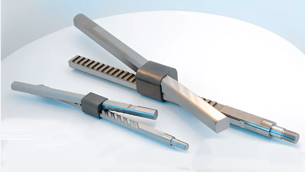
Designing a lifter for injection molding is a complex and technical process that requires careful consideration of many factors. A lifter is a small, movable component used to lift the molded part off the core side of the mold during ejection. It is a critical component in injection molding because it helps create complex geometries and undercuts in molded parts. This article will discuss the detailed and technical process of how engineers conduct the injection mold lifter design process.
The Detailed 9-Step Design Guide:
Below is a detailed injection mold lifter design guide:
Step 1: Analyze the Part Design
The first step in designing a lifter for injection molding is to analyze the part design. The design engineer must understand the part geometry, including any undercuts or other features that may require a lifter. The engineer needs to consider the complexity of the part design and the tolerances required.
Step 2: Determine the Lifter Position and Direction
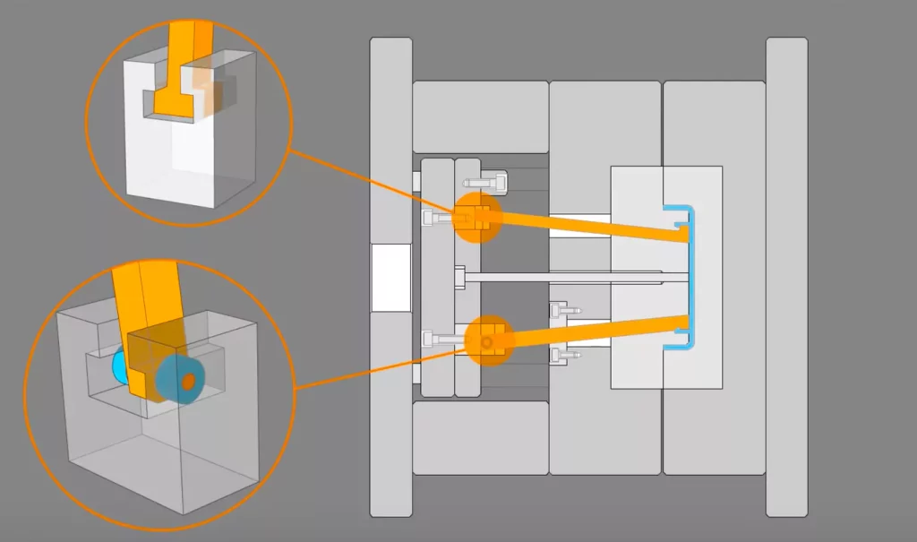
After understanding the part design, it’s crucial to determine the lifter’s position and direction. The lifter’s position is where the engineer fixes it on the mold, and the direction is the angle at which it will move. The engineer must consider the part design and the mold’s construction when determining the lifter’s position and direction. They must also consider the mold’s ejection system and other components that may interfere with the lifter’s movement.
Step 3: Design the Lifter Mechanism
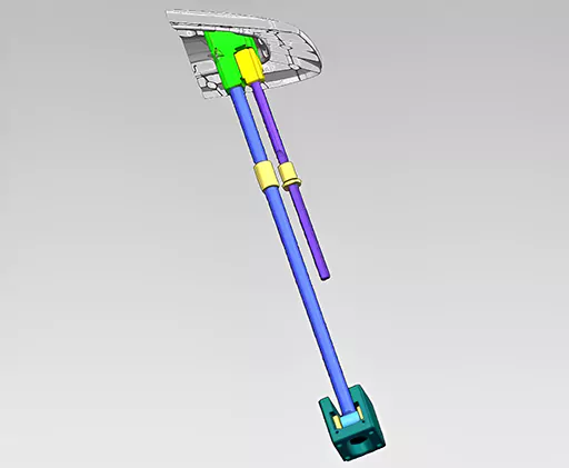
After determining the lifter’s position and direction, they can design the lifter mechanism. The lifter mechanism is the mechanism that moves the lifter. There are several lifter mechanisms, including cam, hydraulic, and mechanical. The engineer needs to consider the type of mechanism that will work best for the part design and the mold’s construction.
Step 4: Determine the Lifter Size and Shape
Once the engineer has designed the lifter mechanism, they must determine the injection mold lifter size and shape. The lifter’s size and shape will depend on the part design and the mold’s construction. The engineer needs to consider the size and shape of the part and the mold’s structure when determining the lifter’s size and shape.
Step 5: Design the Lifter Support Structure
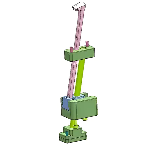
Now once the engineer has determined the lifter’s size and shape, they must design it. The lifter support structure is the structure that supports the lifter in the mold. When designing the lifter support structure, the engineer must consider the mold’s construction and the lifter’s size and shape. Here are some steps to consider when creating the lifter support structure:
Identify the Required Support:
Before designing the support structure, it is essential to identify the areas of the lifter that require support. This may include areas where the lifter contacts the mold or where the lifter may face high stresses or forces. Once the engineer identifies these areas, they determine the type and amount of support required.
Determine the Material:
Select a material for the support structure appropriate for the lifter design and the injection molding process. The material should withstand the forces and stresses the lifter will encounter during operation. It should also be compatible with the mold material and injection molding process.
Determine the Placement of the Support Structure:
The engineer also determines where he should place the support structure in the mold. This may depend on the specific requirements of the injection mold lifter design and the injection molding process. For this, it’s essential to design the support structure to provide the necessary support without interfering with the mold or other components of the injection molding process.
Design the Support Structure:
Design the support structure to provide the required support to the lifter. This may involve creating a separate component that attaches to the mold or integrating the support structure into the lifter design. The support structure should be strong enough to withstand the forces and stresses the lifter will face during operation.
Test the Support Structure:
Test the support structure to ensure it provides the required support to the lifter. Conducting this process using the same testing methods used to test the lifter is essential. Now if the engineer identifies any issues during testing, they modify the support structure as necessary during this phase.
Document the Support Structure Design:
Once designed and tested, document the support structure to replicate it in future injection mold lifter designs. This may include creating detailed drawings or CAD models of the support structure and documenting any materials or manufacturing processes used.
Step 6: Analyze the Lifter Design
Now that the engineer has designed the lifter mechanism, they then the lifter’s size and shape and create the lifter support structure. They need to analyze the injection mold lifter design. When analyzing the lifter design, the engineer needs to consider the part design, the mold’s construction, and the lifter’s movement.
Step 7: Make Modifications to the Lifter Design
Once the engineer has analyzed the design, they may need to modify it. When adjusting the lifter design, the engineer must consider the part design, the mold’s construction, and the lifter’s movement. Some specific steps to consider when modifying the design are:
Identify the Issue:
Before making any modifications, it is crucial to identify the issue with the injection mold lifter design. Engineers do this by analyzing the test results or reviewing the lifter’s design thoroughly. During this process, it is crucial to identify the root cause of the issue to ensure that the modifications will address the problem.
Brainstorm Potential Solutions:
Once engineers identify the issue, brainstorm potential solutions to address the problem. They do this by consulting with other design team members, reviewing previous lifter designs, or researching to identify best practices for similar lifter designs.
Evaluate Potential Solutions:
Evaluate each solution to determine the most feasible and practical. Consider cost, ease of implementation, and impact on the lifter’s performance. It may be necessary to conduct additional testing or analysis to evaluate the potential solutions.
Implement Modifications:
Professionals also modify the lifter design once they identify the best solution. This may involve changing the lifter’s geometry, material, or manufacturing process. Be sure to document the changes made to the design and update any documentation or drawings that the modifications may impact.
Test the Modified Design:
After implementing the modifications, professionals test the modified injection mold lifter design to ensure that they address the issue and that the lifter performs as intended. Use the same testing methods used to test the original design and compare the results to those obtained with the original design. If additional modifications are needed, repeat the process until they resolve the issue.
Please verify that the Modifications So Do Not Create New Issues:
Once the lifter design modifications have been implemented and tested, verifying that the changes have not created any new issues or problems is vital. It is possible by conducting additional testing or reviewing the lifter’s performance during production runs.
Step 8: Produce the Lifter
Now the engineer will produce the lifter according to the finalized design. In this process, they create the lifter by using a variety of manufacturing processes, including machining, casting, and 3D printing. The engineer needs to consider the lifter’s material, the manufacturing process, and size and shape when producing the lifter.
Step 9: Test the Lifter
In this stage, the engineer then tests the lifter. The purpose of trying a lifter is to ensure that the lifter works correctly and to identify any issues the professionals should address before using the lifter in production. Here are some standard methods for testing the design of a lifter:
Moldflow Simulation:
Moldflow simulation software can simulate the lifter’s movement during injection molding. The software can identify any issues with the lifter design, such as interference with other mold components, improper lifter movement, or potential part defects. This method is commonly used in the early stages of the injection mold lifter design process.
Prototype Molding:
Producing a prototype mold with the designed lifter can help to identify any issues with the lifter’s movement, fit, or performance. A prototype mold helps produce a limited number of parts professionals can evaluate for quality and functionality.
Test Molding:
Engineers use a test mold to produce more parts for evaluation. Test molding can help identify any issues they did not detect during prototype molding, such as excessive wear on the lifter or stress on the part. Professionals also use this method when using the lifter in high-volume production.
Mechanical Testing:
Mechanical testing can evaluate the lifter’s strength, durability, and wear resistance. Test the lifter using a variety of automated tests, such as fatigue testing, tensile testing, or hardness testing. The mechanical testing results can help identify any potential issues with the lifter’s design.
Visual Inspection:
Visual inspection can help identify any issues with the lifter’s movement or fit. Professionals inspect the lifter visually to ensure it is moving correctly and not interfering with other mold components. It is also possible to visually inspect the parts produced using the lifter by identifying any defects that lifter issues may cause.
Conclusion:
Overall, designing a lifter for injection molding requires extreme attention, careful consideration, and proper following of each step. And by following these steps, you, as a manufacturing engineer, can ensure a lifter’s quality design to produce different products you plan to manufacture through injection molding.
For more details and queries, feel free to contact us at Prototool.com.


