The automotive dashboard is an integral component of any vehicle’s interior. It serves as both a functional control center and a canvas for style and innovation. In automotive interiors manufacturing, all components related to the dashboard collectively form the dashboard assembly. This assembly includes both the primary dashboard and its complementary sub-dashboard. It plays a pivotal role in balancing safety, comfort, and aesthetics within the vehicle.
Traditionally, dashboards featured soft materials and incorporated safety features such as airbags. However, with advancements in automotive technology, the quest for a harmonious blend between quality and cost-efficiency has driven the rise of rigid dashboard materials. We’ll show two dashboard molding cases in this article. Join us on this journey as we delve into two compelling case studies in the art of dashboard mold and molding. Here, safety, style, and substance unite to enhance the automotive journey.
Case Study One
01. Dashboard Product Analysis
The material makeup of PP (Polypropylene) blended with EPDM-TD20 plays a crucial role in enhancing the dashboard’s resilience. EPDM is an elastomeric compound that enhances the component’s flexibility. Meanwhile, the inclusion of T20, which signifies the addition of 20% talcum powder, increases the dashboard’s rigidity.
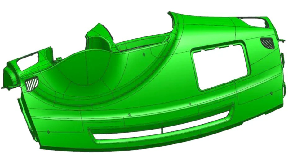
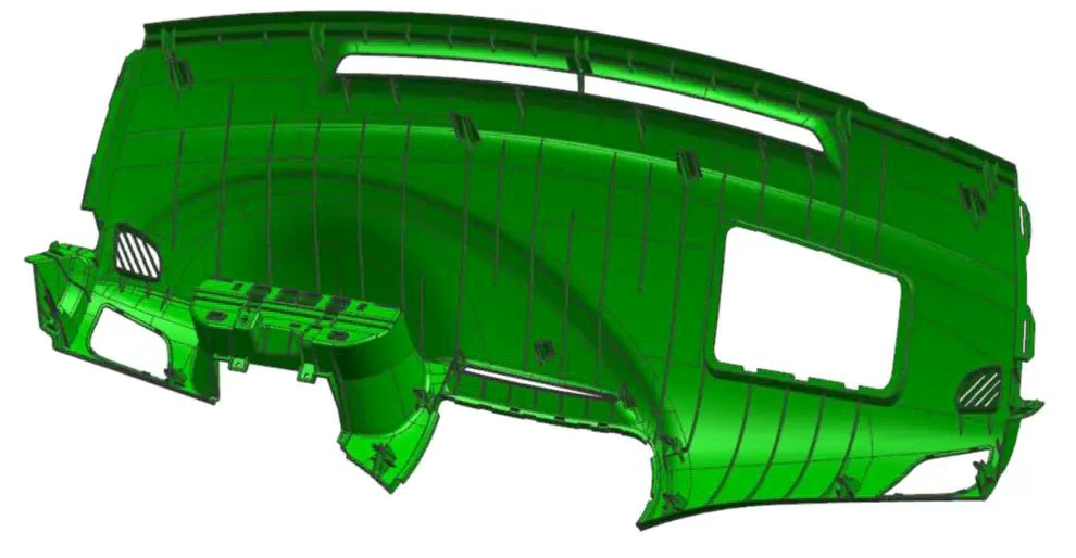
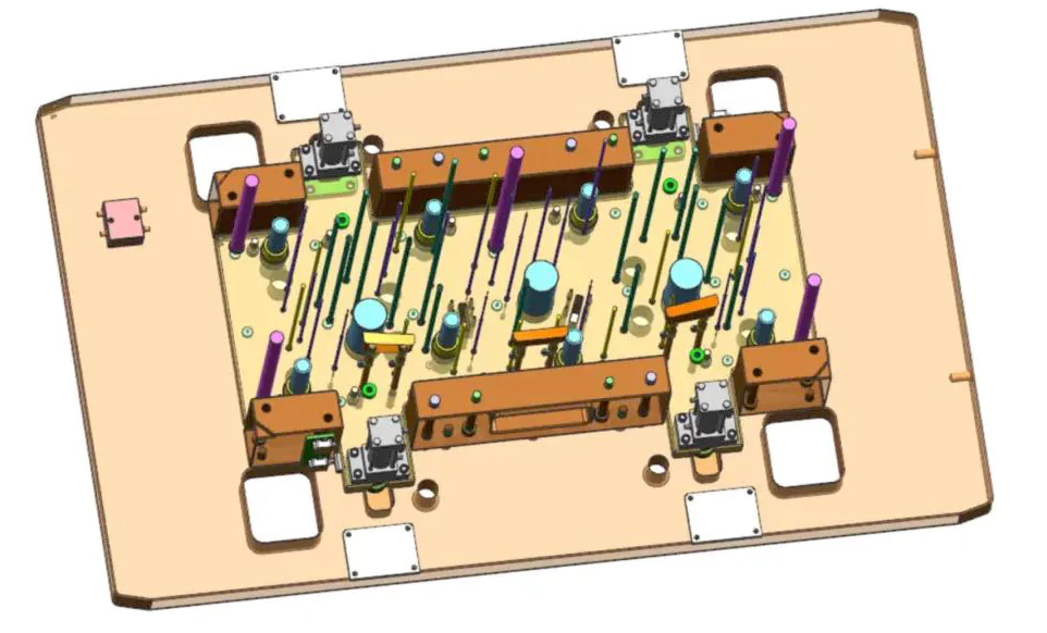
02. The Dashboard Mold Structure Analysis
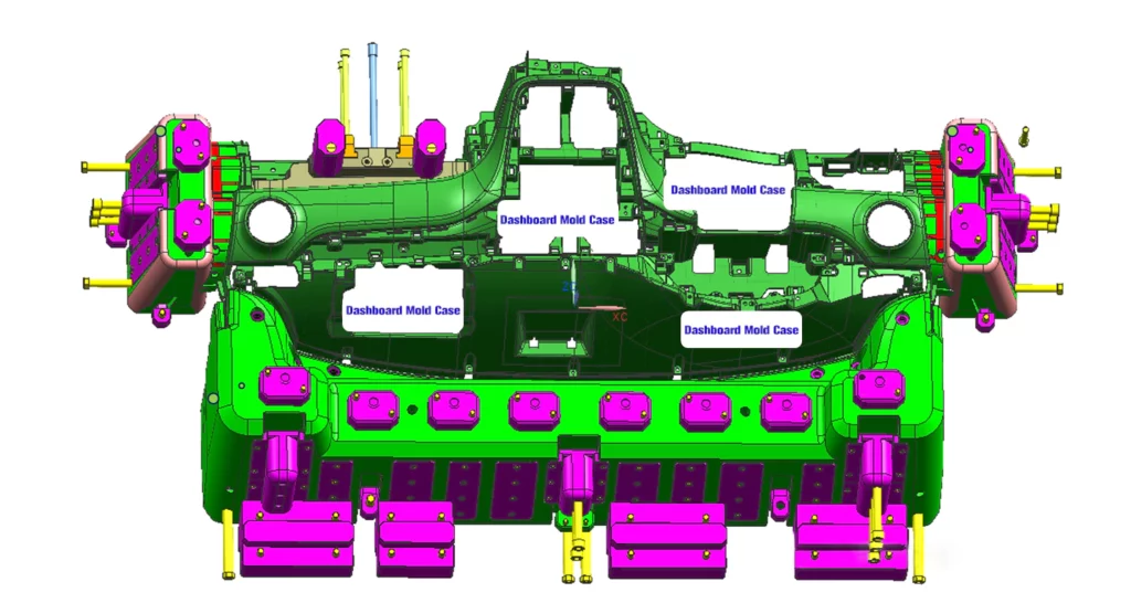
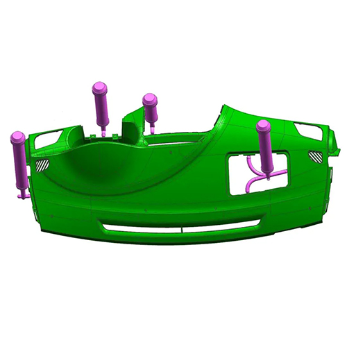
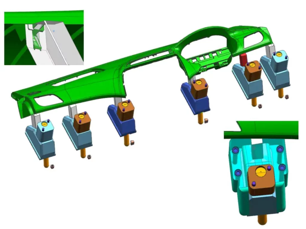
Analyzing the mold’s structure, we find that the dashboard exhibits four distinctive concave-convex structures. These require the implementation of four side actions, as illustrated in the accompanying images. The side actions constitute one of the most vital and intricate aspects of this mold. Slide parts 1, 2, 3, and 4 have a cavity ejection block structure and a side action with hooks and springs.
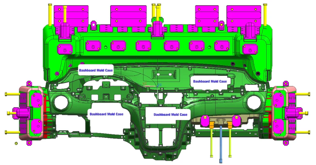
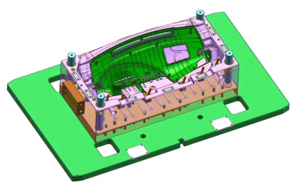
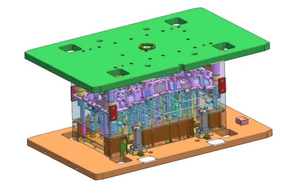
03. Overall Structure of the Dashboard Mold
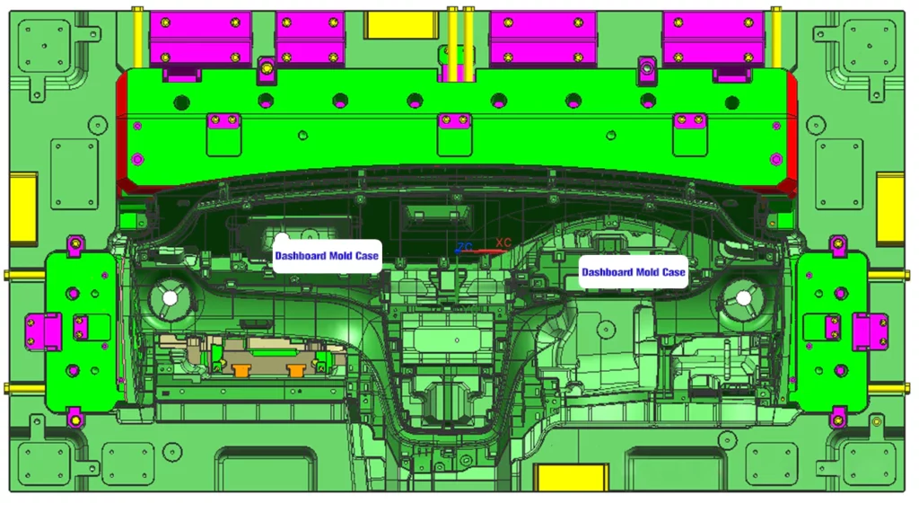
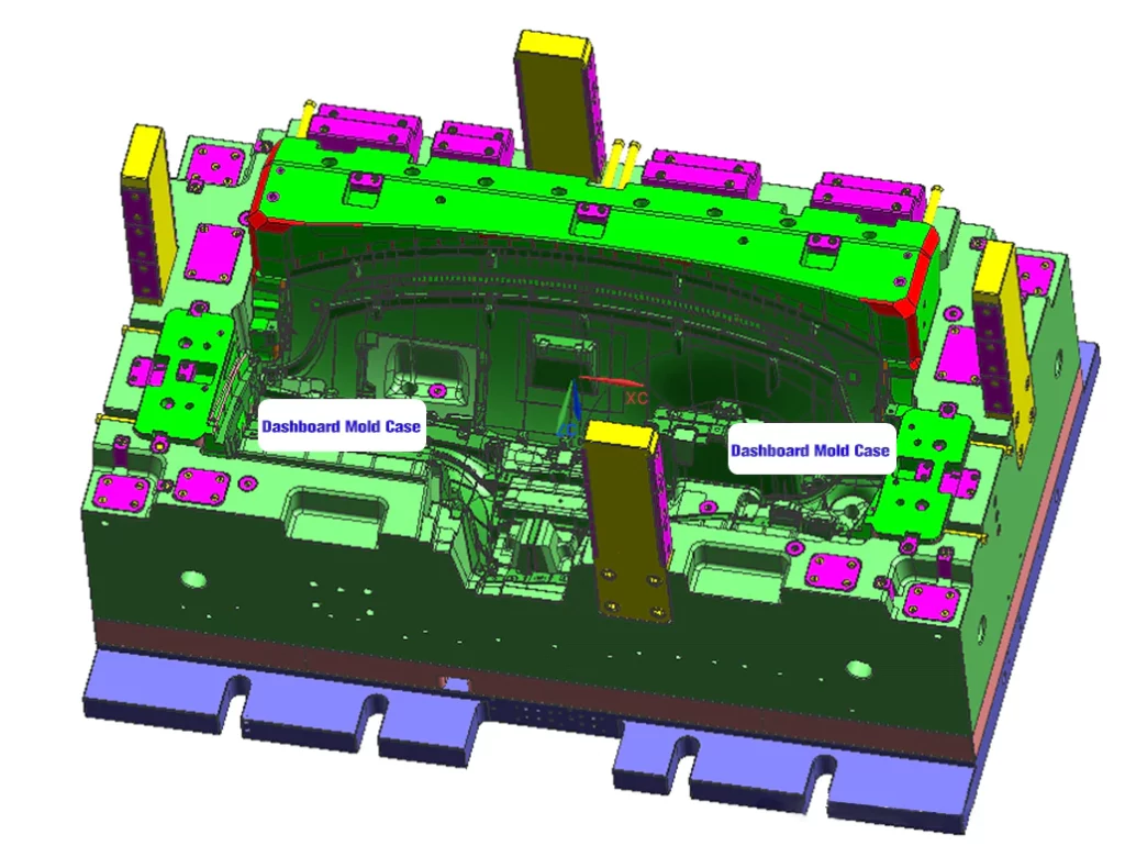
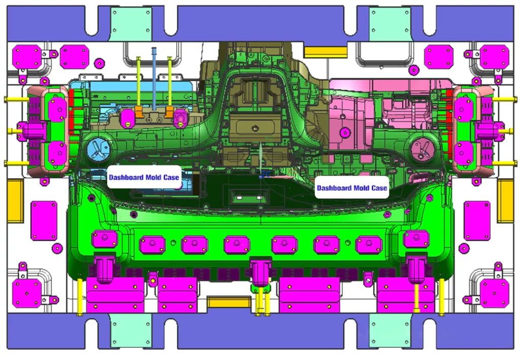
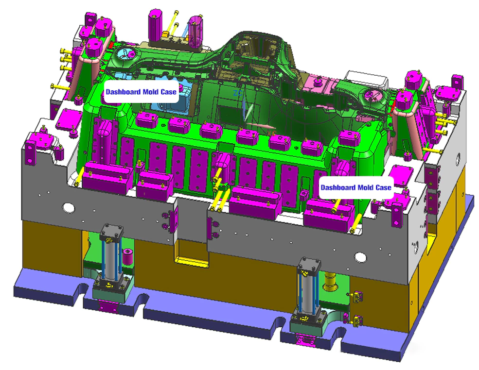
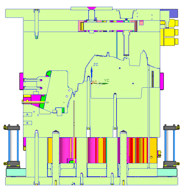
The overall mold structure adopted for the dashboard’s injection process features a hot runner system. Both the cavity and core are designed as a single integral unit, rather than the traditional insert assembly. The mold utilizes square guide pillars and internal mold pipe positioning for accurate alignment. For the core part, we use an insert assembly structure. The precise guidance and positioning systems between the cavity and core determine the accuracy of the final product. They also significantly impact the mold’s service life. In this particular mold, four square guide pillars ensure proper alignment.
Case Study Two
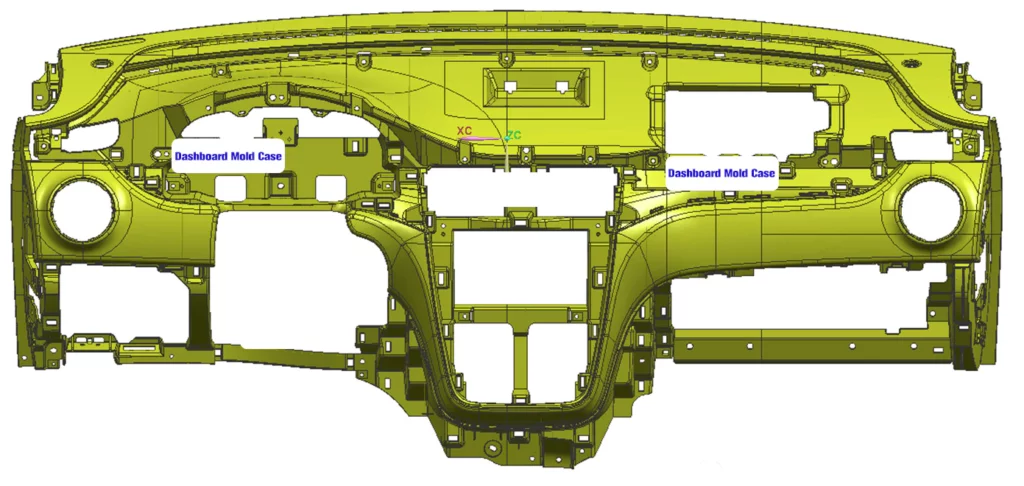
Dashboard Product Analysis
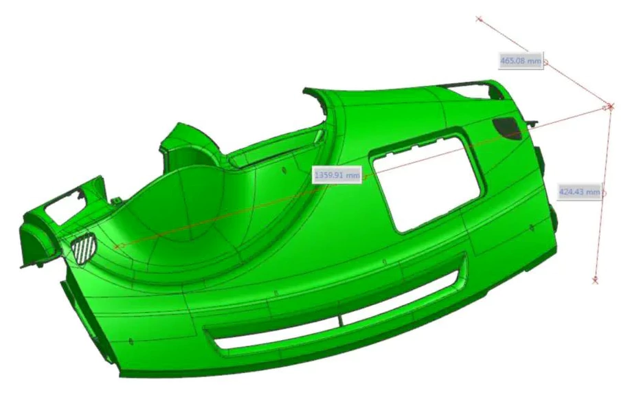
In our second case study, we continue dashboard molding analysis, where precision and attention to detail are paramount. This time, our focus is on a substantial automotive dashboard component, measuring an impressive 1359.9 x 465.08 x 424.43 millimeters. This dashboard is made from a blend of PP (Polypropylene) and EPDM-TD22. It showcases the perfect union of materials that enhance both flexibility and strength.
The stuff that makes up the dashboard is super important for how well it works. We use EPDM (Ethylene Propylene Diene Monomer) to enhance the component’s elasticity. Additionally, the inclusion of TD22, representing a 22% addition of talcum powder, bolsters the dashboard’s structural integrity. The exterior features a textured finish. A vital requirement is for the demolding angle to be equal to or exceed 5 degrees.
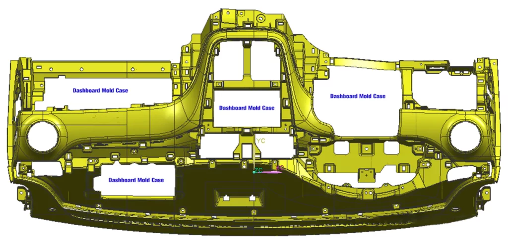
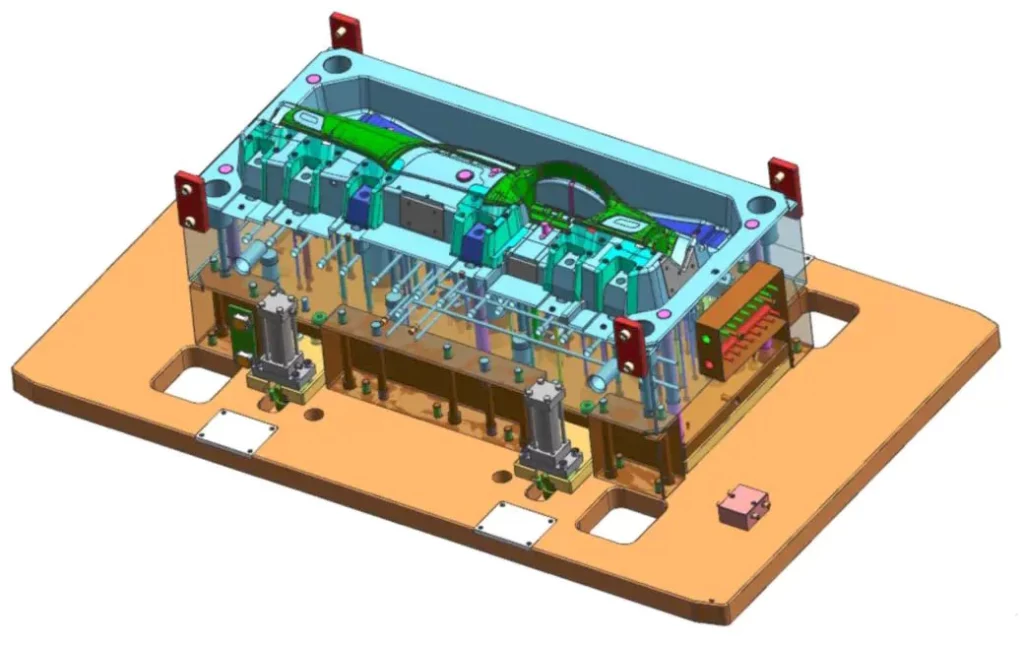
02. Dashboard Product Structure Analysis
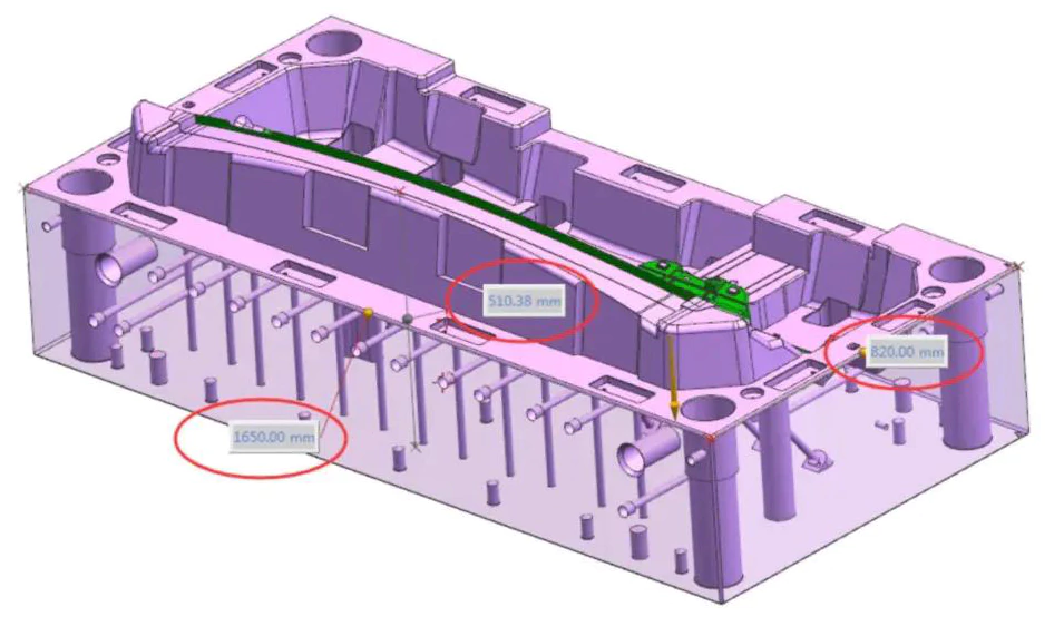


Diving into the dashboard’s structural blueprint, it becomes evident that precise design is at the core of this case. The fixed mold core dimensions are 1650 x 820 x 510.5 millimeters. This design ensures that the lowest point maintains a 201.5-millimeter distance from the core base. It is an extension of 100 millimeters beyond the dimensions of the cavity. The lateral surfaces each retain 99 millimeters and 91 millimeters, with a consideration of the steel’s tensile strength.
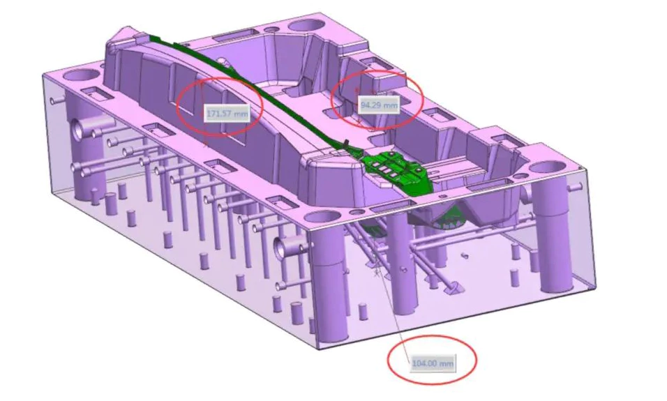
Looking into the seal-off dimension, the component features approximately 180 millimeters from the seal-off position. The closest point to the adhesive measures 142.5 millimeters, with a 65-millimeter shut-off, drawing from data from previous work to ensure a sturdy construction. The highest point on the component leaves 171 millimeters for the demolding surface, an approximation that accounts for one-third of the product’s overall height. Additionally, the lowest point for the rubber position to the core base retains a 104-millimeter distance.
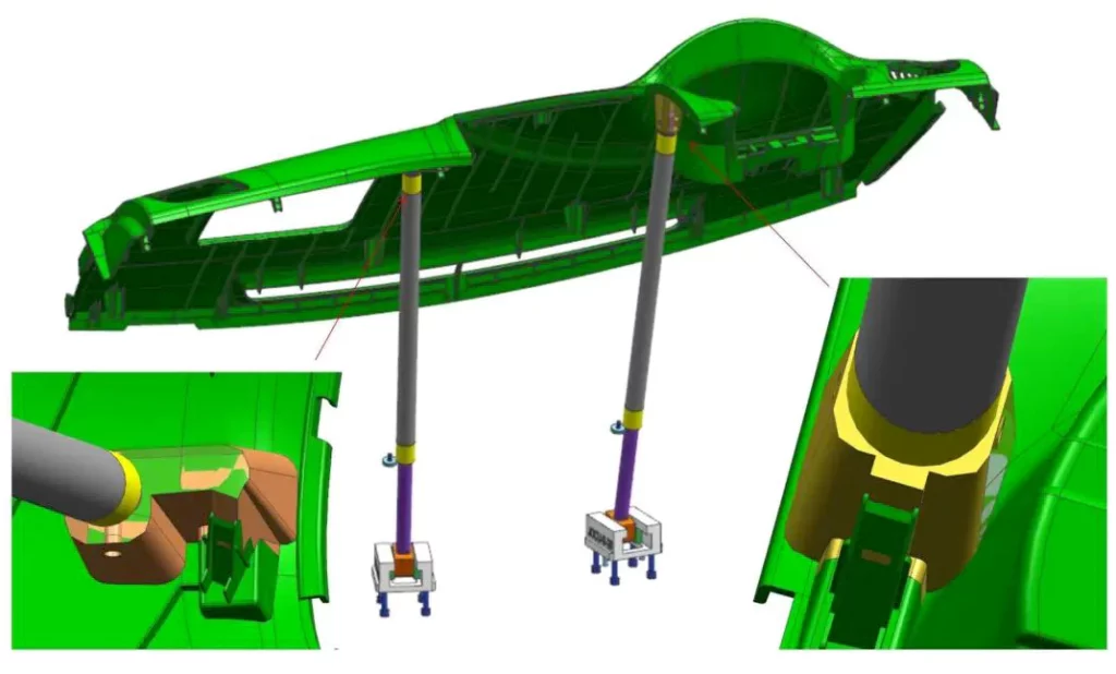
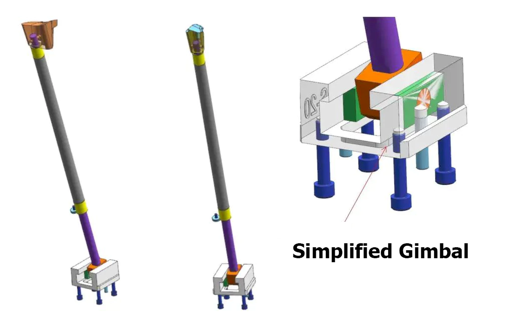
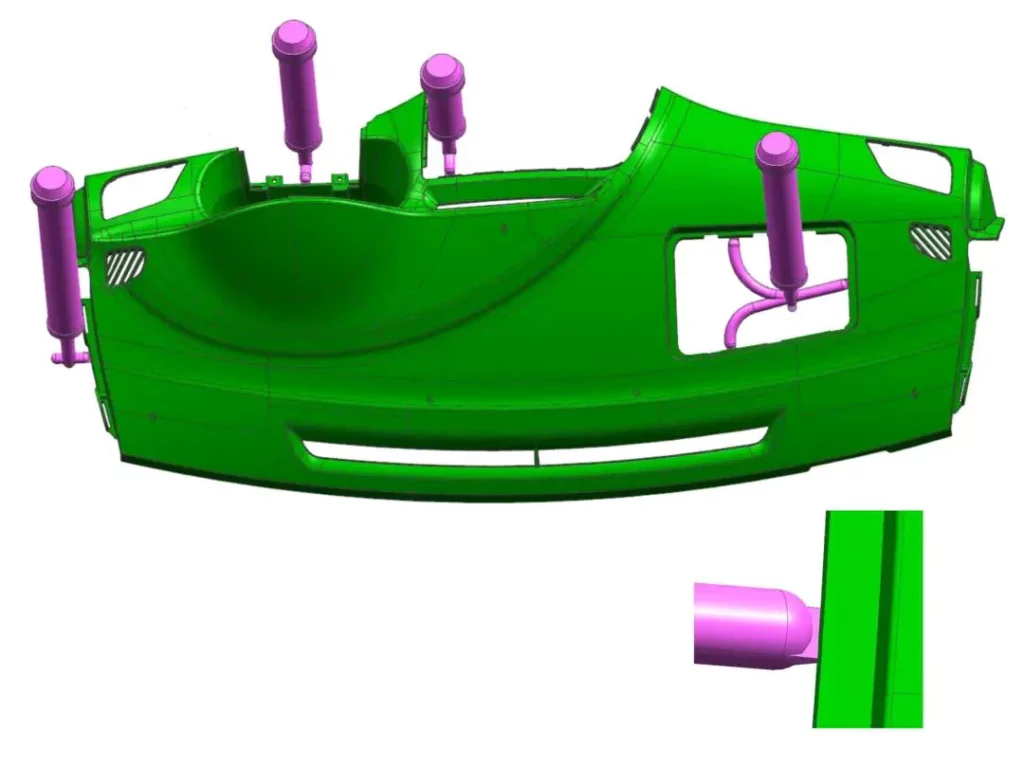
This case has six angled-lift splits of the core, designed for easy manufacturing. We construct all slanting grooves from the front and inset them as components. It also includes two lifters, one at a 14-degree angle and the other at a 13-degree angle. These tops are affixed using cylindrical dowels and are complemented by a three-section guide bushing along with a simplified universal seat design.
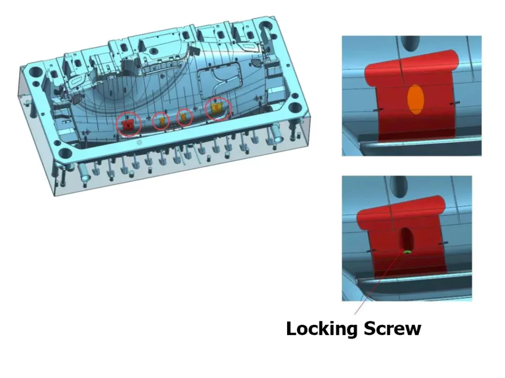
We secure the front of the rib blind inserts, a vital part of the case, with lock screws, and fill the screw’s top surface with copper. We position these blind inserts on the component’s slanted surface. Due to high injection pressure, a precise positioning mechanism is necessary to avoid deformation.
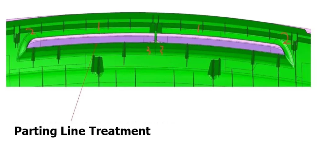
The dashboard product undergoes a parting line treatment of the guiding surface, starting with a simplified large surface formed along the parting line. Subsequently, the mesh curve bridges the two sides, culminating in an inverted R-corner.
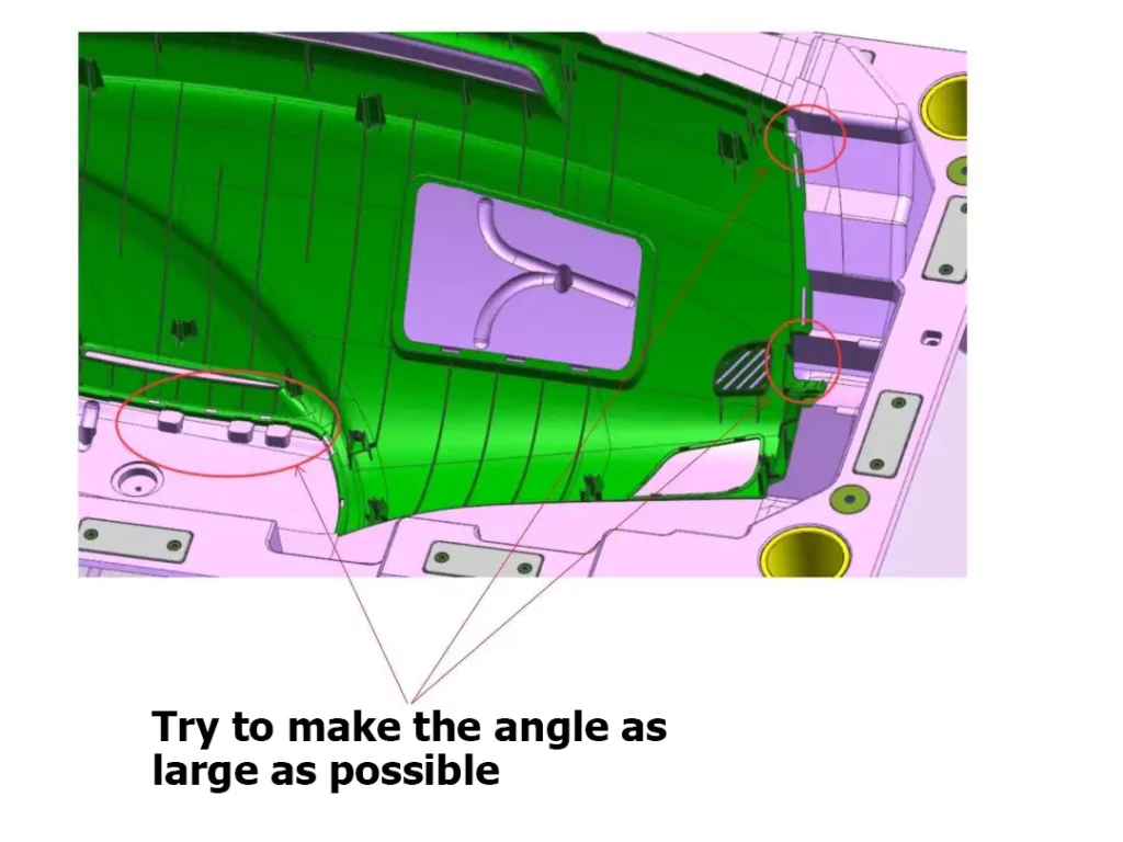
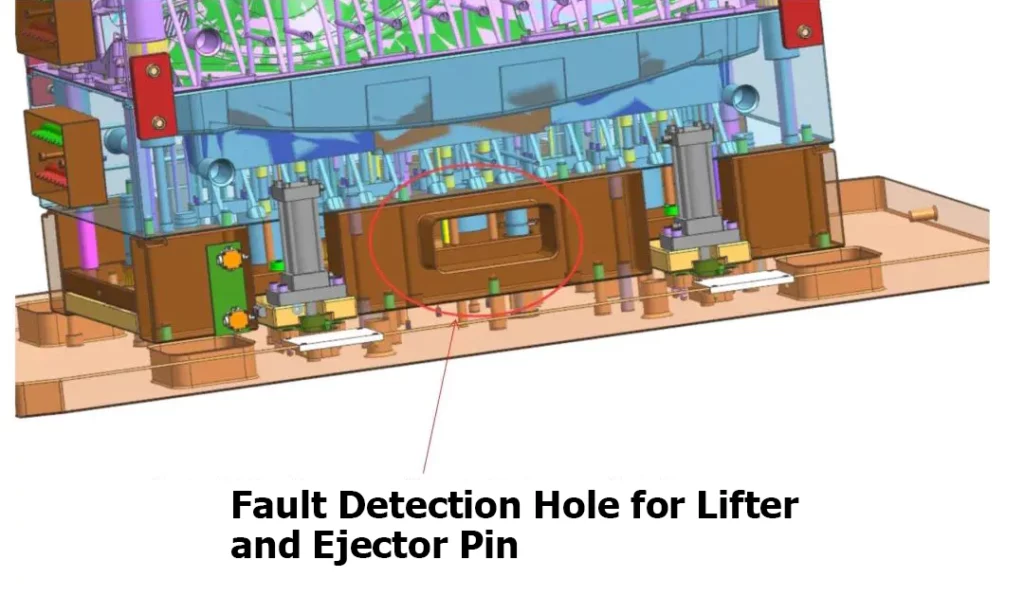
The case also highlights the necessity of ensuring that minor deflashing angles are at least 5 degrees, with an effort to maximize the angle. Both sides of the panel are designed with gradient guides to facilitate assembly on the injection molding machine. The inclusion of a fault detection orifice for the angled tops simplifies and streamlines troubleshooting during mold maintenance, which is particularly significant for large molds.
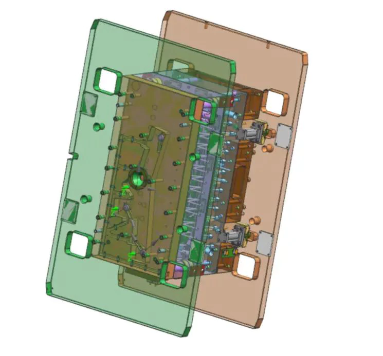
The conventional mold design employs pillar-and-bushing guiding systems, with the bushings crafted from bronze graphite. The front assembly involves pillars that are twice the diameter of the pillars used, securing the bottom with lock screws. These pillars feature an incline for proper alignment, a crucial design element considering the mold’s size and the challenges associated with aligning it.
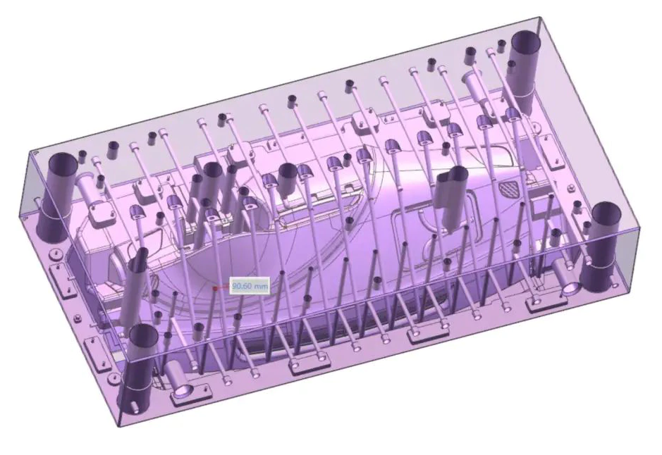
Regarding the cavity, we apply a cooling design based on the product’s form. It has a direct-injection water diameter of 14 millimeters and spaces 90 millimeters apart for even distribution. This design lets water flow directly in and out without passing through O-rings.
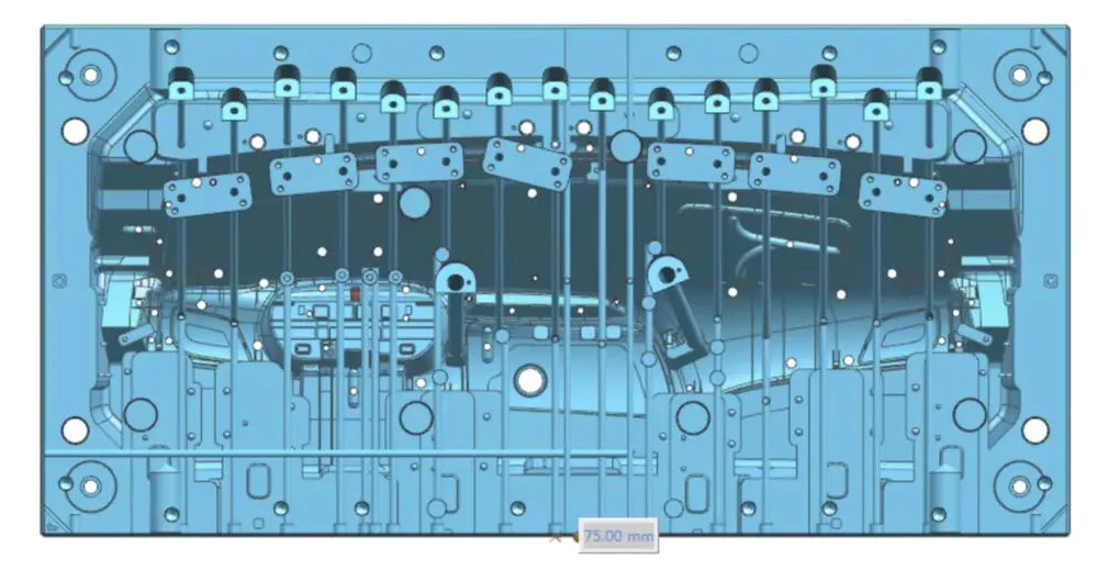
We use a similar cooling design for the core, featuring a water diameter of 12 millimeters and spaces 75 millimeters apart. For deeper areas, we include water wells to ensure even distribution and direct water flow in and out, eliminating the need for O-rings.
03. Ejector System
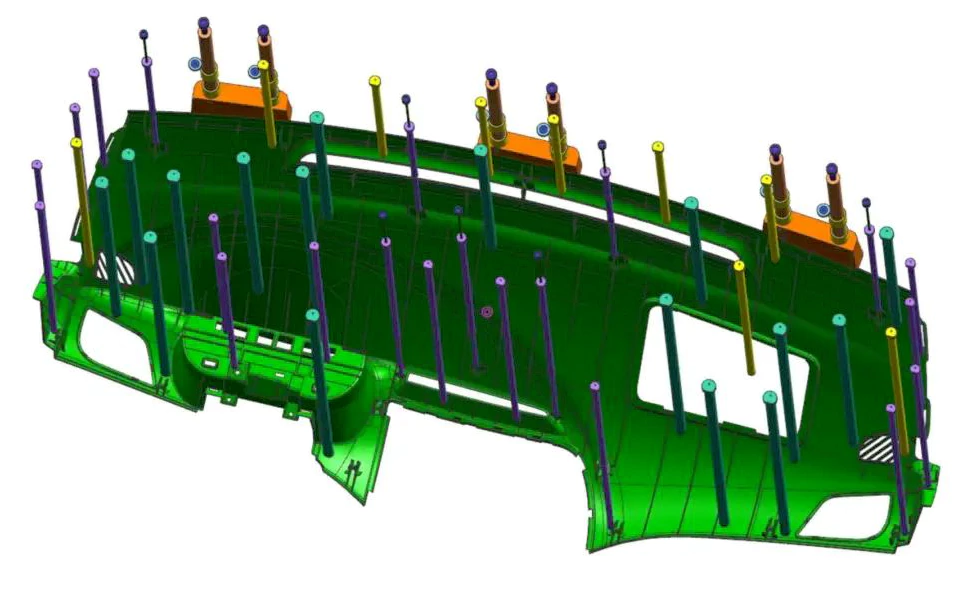
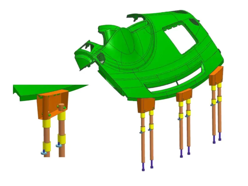
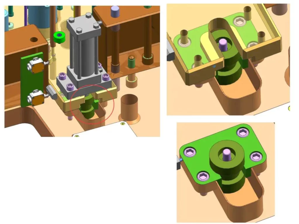
We use a combination of lifters, eject pins, ejector sleeves, and push blocks to eject the product. The top pins have a diameter ranging from 8mm to 16mm, with cylindrical screws situated beneath the ejector sleeves. To prevent slipping on slanted surfaces, we use four oil cylinders that facilitate ejection in molds measuring 1650mm in length. The design also includes five return pins and eight intermediate-support pilot pins. Such measures are essential for molds of considerable length, as they require the inclusion of return pins for proper alignment.
The oil cylinders have a simple and practical design that allows side installation and features pressure blocks on the base plate to secure the oil cylinder joints. This design also ensures easy assembly and disassembly.
04. Dashboard Assembly
In the final assembly, you must equip diagonal measurement sensors at the oil cylinder’s corners, installing one both above and below.