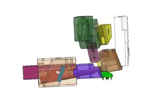
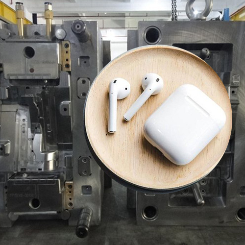
In mold design, our journey has taken us through a myriad of plastic products, from automotive components and household appliances to consumer electronics and everyday items. Yet, our encounters with audio products, particularly earphones, have been relatively limited. These products, with their distinct structures and stringent aesthetic demands, present a unique set of challenges. Today, we’re excited to share an in-depth analysis of a classic Bluetooth earphone shell mold, offering insights into its intricate design and hoping to inspire fellow enthusiasts and professionals in the field.
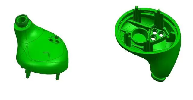
Analyzing the Intricacies of Bluetooth Earphone Mold Design
When diving into the design intricacies of Bluetooth earphone molds, it’s evident that precision and attention to detail are paramount. The mold’s structure, especially for such a delicate product, requires meticulous planning and execution.
Slope Analysis and Undercuts
A slope analysis reveals undercuts in both the left and right directions of the earphone shell. These undercuts, primarily located in the front mold, demand strict aesthetic requirements. To address this, sliders on both sides are designed as front mold tunnel sliders. Additionally, there’s a slanted hole at the top of the product. Given the limited space within the mold, this section should be designed with a front mold slant pull. It’s crucial to ensure the proper installation and fixation of this pin. Another undercut is present inside the product, which is considered for a slant top design.

Precision in Circular Undercuts
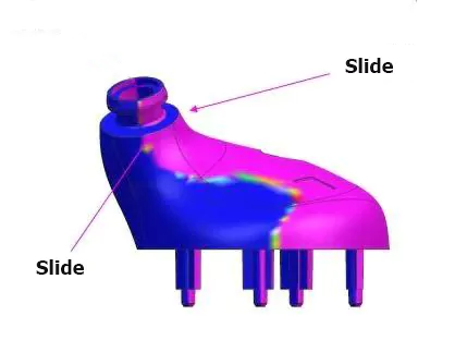
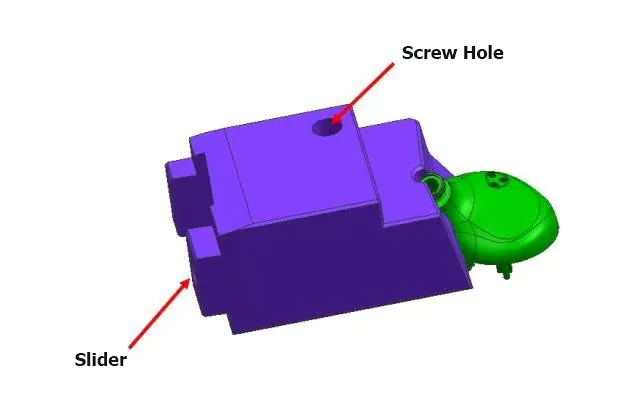
The product’s mouth section has a circular undercut. The sliders on both sides employ a half-slider overlap design. Given the high precision required for earphone mold designs and the strict aesthetic demands, these types of sliders are designed with technical screw holes. The primary purpose of these screws is to ensure the slider’s installation in the front mold, eliminating the need for clamping lines.
Right Side Undercut Design
The right side of the Bluetooth earphone features an undercut with a certain slant. The slider’s demolding direction aligns with the product’s undercut direction. Due to spatial constraints, only one side of the T-foot of the slider is pressed. When designing this slanted slider, it’s essential to note the high product requirements and the need for technical screws. The connection method for the slider uses a T-slot connection due to space limitations.

Ensuring Slider Strength
The top of the Bluetooth earphone product features a slanted hole. To guarantee the strength of the slanted slider, the back part of the slider is designed as a square, utilizing a T-slot to connect to the slider seat. The primary source of power for the front mold core pulling comes from the injection molding machine’s opening force or springs. Due to space constraints, the slider’s limit is designed on a small T-block. It’s vital to ensure that after the slider core pulling completes its journey, at least one-third remains inside the slider seat for safe mold closure.

Movement Principle of the Bluetooth Earphone
When the mold opens, the injection molding machine’s opening force ensures the front mold core pulling completes first. Simultaneously, the front mold’s slanted slider also completes its core pulling action. As the front mold’s large slanted slider is fixed on the large slider seat, it moves with the large slider after reaching a certain opening degree. Finally, the A and B plates open, the product is ejected, and the overall earphone structure in the front mold is revealed.
