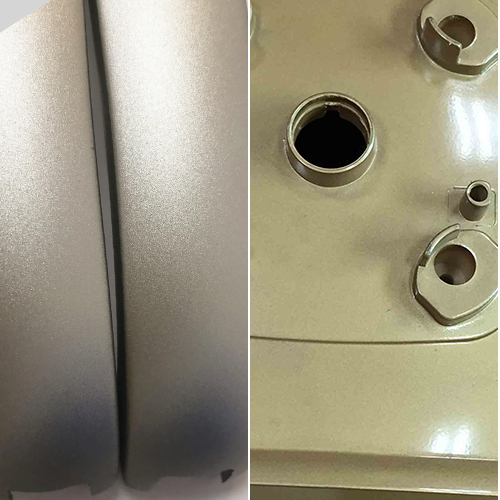
When it comes to the world of injection molding, ensuring the quality and efficiency of your moules d'injection is paramount. As a customer, you’re not just investing in a piece of equipment; you’re investing in the future of your product, its quality, and your brand’s reputation. But how can you be certain that the mold you’re accepting meets the highest standards?
First and foremost, a top-tier mold should consistently produce high-quality products. It should be designed to integrate seamlessly into your production process, promising longevity and efficiency. But beyond these basics, there are specific standards and criteria that your mold should meet.
In this article, we’ll delve deeper into these standards, providing you with a comprehensive guide on what to look for during mold acceptance. We’ll give you all the information you need to make a smart choice about the mold, including how it looks, what it’s made of, how it stays cool, and how it’s made. This way, you can be sure you’re getting the most value from your investment.
Key Criteria for Injection Mold Product Acceptance
Lorsqu'il s'agit de la acceptance of injection-molded products, it’s crucial to have a clear understanding of the standards that ensure the product’s quality and functionality. Here’s a breakdown of the essential criteria for injection mold product acceptance:
- Surface Appearance and Defects: The product’s surface should be free from defects tels que coups courts (insufficient material), marques de brûlures, marques d'évier, ejected marks, lignes de soudure, bulles, splay marks (also known as silver streaks), and any signs of tearing or cracking.
- Lignes de soudure: For standard round holes, the weld line length should not exceed 5mm. For irregularly shaped holes, the weld line length should be less than 15mm. Moreover, the strength of these weld lines should pass functional safety tests.
- Rétrécissement: Visible surfaces should not show any signs of shrinkage. In less noticeable areas, minimal shrinkage is acceptable as long as it’s not tactilely detectable.
- Déformation: For smaller products, the flatness deviation should be less than 0.3mm. Products that require assembly should meet all assembly specifications.
- Surface Imperfections: The product should not have flow lines or material residues. Bubbles are generally not acceptable.
- Geometric Accuracy: The product’s geometric shape and size precision should align with the official and valid mold drawings or 3D file requirements. Tolerances should adhere to standard principles: shaft dimensions should have negative tolerances, while hole dimensions should have positive ones. Any specific customer requirements should be met.
- Épaisseur de la paroi: Le product’s wall thickness should generally be uniform. Any deviations from uniformity should align with the drawing specifications. Based on the mold’s characteristics, the tolerance should be maintained at -0.1mm.
- Product Fit: When it comes to the fit between the top and bottom shells, the surface misalignment should be less than 0.1mm. Make sure there aren’t any pointy or rough parts that might hurt someone. Any holes, shafts, or surfaces that require fitting should ensure proper spacing and meet usage requirements.
Aesthetic and Functional Standards for Injection Mold Exteriors
The exterior appearance and functionality of an injection mold play a pivotal role in ensuring the quality of the molded product. Here’s a comprehensive guide on the aesthetic and functional standards for injection mold exteriors:
- Mold Nameplate: The nameplate should be complete with clear and neatly arranged characters.
- Nameplate Positioning: It should be securely affixed near the mold foot, close to the template and reference corner. The nameplate should be firmly attached and not prone to peeling off.
- Cooling Water Nozzles: Ideally, plastic block water nozzles should be used unless the customer specifies otherwise.
- Nozzle Protrusion: The cooling water nozzle should not extend beyond the fond de moule surface.
- Nozzle Recess: The nozzle should have a recessed hole, with diameters available in 25mm, 30mm, and 35mm specifications. The hole should have a chamfer, and the chamfering should be consistent across all nozzles.
- Nozzle Markings: Each nozzle should be marked to indicate the water’s entry and exit points.
- Marking Clarity: English characters and numbers used for markings should be larger than 5/6. They should be positioned 10mm directly below the nozzle, ensuring clarity, aesthetics, neatness, and uniform spacing.
- Mold Accessories: They should not hinder the mold’s lifting or storage. If there are exposed cylinders, water nozzles, or pre-reset mechanisms at the bottom during installation, they should be protected by support legs.
- Support Leg Installation: Screws should be used to secure the support legs to the mold base. If a support leg is too long, it can be machined with external threads and then fastened to the mold base.
- Mold Ejection Hole Size: It should meet the requirements of the specified injection machine. Except for small molds, a single central ejection should not be used.
- Location Ring: It should be securely fixed, with diameters of 100mm and 250mm. The anneau de localisation should protrude 10-20mm from the base plate, unless the customer specifies otherwise.
- Mold Dimensions: They should comply with the requirements of the designated injection machine.
- Directional Markings: Molds with specific installation directions should have an arrow indicating the direction on the front or rear template. The arrow should be accompanied by the word “UP,” both in yellow and with a character height of 50mm.
- Mold Base Surface: It should be free from dents, rust, excess lifting rings, water and oil holes, and any defects that affect its appearance.
- Mold Handling: The mold should be easy to lift and transport. During lifting, mold components should not be disassembled, and lifting rings should not interfere with water nozzles, cylinders, or pre-reset rods.
Material Selection and Hardness Criteria for Injection Molds
The choice of materials and their hardness levels is crucial in the construction of injection molds. These factors directly influence the mold’s durability, performance, and the quality of the final product. Here’s a guide on the material and hardness standards for injection molds:
- Standard Mold Base: The mold base should be selected based on established standards. Using a standardized mold base ensures consistency and compatibility with various injection machines.
- Mold Forming Parts and Gating System: The materials used for forming parts and the système de portillon (including the core, movable and fixed mold inserts, split inserts, bagues de carotte, push rods, and gate sleeves) should possess properties superior to those of 40Cr. This ensures that the mold components can withstand the pressures and temperatures of the injection molding process.
- Résistance à la corrosion: When molding plastics that are corrosive to the mold, the forming parts should be made of corrosion-resistant materials. Alternatively, the molding surface should have anti-corrosion measures in place. This prolongs the la durée de vie des moisissures and ensures consistent product quality.
- Hardness of Mold Forming Parts: The hardness of the mold-forming parts should not be less than 50HRC. Alternatively, if surface hardening treatments are applied, the hardness should exceed 600HV. A higher hardness level ensures that the mold can resist wear and tear, leading to longer mold life and consistent product output.

Ejection, Resetting, Core Pulling, and Part Retrieval Standards
In injection molding, the process of ejecting, resetting, core pulling, and part retrieval is paramount. These steps ensure that the molded parts are released smoothly and that the mold is ready for the next cycle. Here’s a comprehensive guide on the standards for these processes:
- Smooth Ejection: The ejection process should be smooth, without any jamming or unusual noises.
- Angled Ejection: The surface of the angled ejector should be polished and should be lower than the core surface.
- Sliding Components: These components should have oil grooves and undergo nitriding treatment, resulting in a surface hardness of over HV700.
- Ejector Rods: All ejector rods should have rotation stoppers and be numbered for easy identification.
- Ejection Distance: Limit blocks should be used to control the ejection distance.
- Reset Springs: Standard parts should be used for reset springs. Both ends of the springs should remain unaltered.
- Slider and core Pulling: There should be travel limits. Small sliders can use spring limits, while hydraulic core pulling should have travel switches.
- Core Pulling with Sliders: Generally, angled guide posts are used. If the slider’s travel is too long, hydraulic extraction should be employed.
- Hydraulic core Locking: If the end face of the hydraulic core forming part is covered, a self-locking mechanism should be added.
- Wear Plates for Large Sliders: For sliders wider than 150mm, wear plates made of T8A material, hardened to HRC50~55, should be used.
- Ejector Rod Movement: Ejector rods should not move up and down during operation.
- Ejector Rod Hooks: Hooks on ejector rods should be consistent in direction and easily removable from the product.
- Ejector Rod Hole Specifications: The gap between the ejector rod hole and the rod, the length of the sealing section, and the surface roughness of the hole should meet relevant company standards.
- Product Retrieval: Products should be easily retrievable by operators.
- Ejector Rod Grooves: If a product tends to follow the angled ejector during ejection, grooves or etchings should be added to the ejector rod.
- Ejector Blocks: These should be securely fixed to the ejector rods, with a 3°~5° slope on the non-forming parts and chamfered edges at the bottom.
- Oil Circuit Cleanliness: The oil circuit holes in the mold base should be free of debris.
- Return Rod Specifications: The end face of the return rod should be flat, without spot welding.
- Three-Plate Mold Gate Plate: The guiding of the gate plate should be smooth, and the gate plate should be easily pulled open.
- Three-Plate Mold Limit Rods: To ensure that these don’t obstruct the people working with the mold, position them on both sides of the mold’s installation direction.
- Oil and Air Channels: These should be unobstructed, and hydraulic ejection resetting should be accurate.
- Guide Sleeve Venting: The bottom of the guide sleeve should have venting holes.
- Positioning Pin Installation: There should be no gaps in the installation of positioning pins.
Cooling and Heating System Standards
Les cooling and heating systems in injection molding are crucial for making sure the molding process works well. If these systems are designed and taken care of properly, they can make the molding process faster and produce better-quality parts. Here’s a guide to the standards for these systems:
- System Flow: The cooling or heating system should have an unobstructed flow, ensuring optimal temperature control throughout the molding process.
- Reliable Sealing: The system’s sealing should be dependable. Under a pressure of 0.5MPa, there should be no leakage, making it easy for maintenance and inspections.
- Sealing Groove Specifications: The dimensions and shape of the sealing grooves on the mold base should comply with relevant standards, ensuring a tight fit and preventing any potential leaks.
- Seal Ring Installation: When installing seal rings, they should be lubricated with yellow grease. Once placed, they should protrude slightly above the mold base surface, ensuring a tight seal.
- Flow Path Materials: The materials used for water and oil flow paths should be resistant to corrosion. This ensures longevity and reduces the risk of contamination.
- Centralized Water Supply: Both the front and back molds should utilize a centralized water supply method. This ensures uniform cooling or heating, leading to consistent mold temperatures and improved product quality.
Standards for the Sprue System
The sprue system is a critical component of the injection molding process, ensuring that the molten plastic is efficiently and uniformly distributed throughout the cavité du moule. Adhering to the right standards for this system is essential for producing high-quality products. Here’s a guide to understanding and implementing the right practices:
- Sprue Placement: The placement of the sprue should not compromise the appearance of the product and should facilitate assembly.
- Design du coureur: The cross-section and length of the runners should be thoughtfully designed. Aim to shorten the flow path and reduce the cross-sectional area to minimize filling and cooling times. The plastic loss in the sprue system should be minimized to ensure efficiency.
- Three-Plate Mold Runners: For a three-plate mold, the runner’s section on the back of the front mold plate should be trapezoidal or semi-circular.
- Sprue Puller Design: In three-plate molds, there should be a sprue puller on the sprue plate. The entrance diameter of the runner should be less than 3mm, with a 3mm deep step recessed into the sprue plate at the ball head.
- Sprue Puller Rod Stability: The sprue puller rod should be securely fixed, either pressed under the locating ring, secured with a set screw, or held down with a clamp plate.
- Usinage de précision: Sprues and runners should be machined according to the design specifications. Manual grinding or polishing is not acceptable.
- Point Gate Standards: The point gate should adhere to specific standards and design criteria.
- Cold Slug Well: The front end of the runner should have an extended section to act as a cold slug well.
- Smooth Transitions: The Z-shaped undercut on the sprue puller should have a smooth transition.
- Alignement: The runner on the parting surface should be circular, ensuring no misalignment between the front and back molds.
- Submerged Gate Quality: Submerged gates on the sprue puller rod should exhibit no surface shrinkage.
- Transparency Standards: The diameter and depth of the cold slug well for transparent products should meet design standards.
- Easy Sprue Removal: The sprue should be easily removable, leaving no trace on the product’s appearance or assembly areas.
- Treatment for Hooked Submerged Gates: For hooked submerged gates, both sections of the insert should undergo nitriding treatment, achieving a surface hardness of HV700.
Hot Runner System Standards
Les système de canaux chauds is an integral part of the injection molding process, ensuring that the molten plastic remains at the optimal temperature as it flows through the mold. Adhering to the right standards for this system is crucial for producing high-quality products. Here’s a guide to understanding and implementing the right practices:
- Wiring Layout: The layout of the hot runner wiring should be logical, facilitating easy maintenance. Each wire should be clearly labeled and correspond to its designated connection.
- Safety Testing: The hot runner system should undergo safety tests, ensuring a ground insulation resistance greater than 2MW.
- Standard Components: The temperature control cabinet, hot nozzle, and hot runner should utilize standardized parts.
- Main Sprue Connection: The main sprue should connect to the hot runner using threads, ensuring a flat surface contact for sealing.
- Heating Element Contact: Make sure the hot runner touches the heating plate or rod really well. The heating plate should be securely fastened with screws or studs, ensuring a smooth surface fit.
- Thermocouple Type: Use a J-type thermocouple that matches the temperature control meter.
- Controlled Heating: Each heating element group should have a thermocouple control, with the thermocouple placed strategically.
- Nozzle Design: The nozzle should meet the design specifications.
- Hot Runner Positioning: The hot runner should have reliable positioning, with at least two locating pins or secured with screws.
- Insulation: Placer un tampon isolant entre le canal chaud et la plaque du moule.
- Contrôle de la température: L'écart entre la température de consigne et la température réelle affichée par le thermorégulateur doit être inférieur à ±5°C, ce qui garantit un contrôle sensible de la température.
- Installation de la cavité et de la buse: La cavité du moule et le trou d'installation de la buse doivent être alignés.
- Groupement de câblage: Regrouper le câblage du canal chaud et le recouvrir d'une plaque de presse.
- Étiquetage des prises: S'il y a deux prises de même spécification, elles doivent être clairement identifiées.
- Câblage protégé: Tous les fils de contrôle doivent être protégés par une gaine et ne présenter aucun signe de détérioration.
- Armoire de contrôle de la température robuste: L'armoire de thermorégulation doit être robuste et ne doit pas comporter de vis desserrées.
- Placement des prises: Installer les prises sur une plaque isolante en veillant à ce qu'elles ne dépassent pas les dimensions maximales de la plaque de moulage.
- Câblage externe: Les fils ne doivent pas être exposés à l'extérieur du moule.
- Transitions arrondies: Toutes les zones du canal chaud ou de la plaque du moule en contact avec les fils doivent présenter des transitions arrondies.
- Intégrité du circuit: Avant d'assembler la plaque de moulage, assurez-vous que tous les circuits sont exempts de courts-circuits ou de ruptures.
- Connexions de câblage: Toutes les connexions électriques doivent être correctement raccordées et présenter de bonnes propriétés d'isolation.
- Vérifications du multimètre: Après avoir serré la plaque du moule, vérifiez à nouveau tous les circuits à l'aide d'un multimètre.
Section de moulage, plan de joint et rainures d'aération
La section de moulage, le plan de joint, et ventilation groves jouent un rôle essentiel dans le processus de moulage par injection. Il est essentiel de veiller à ce que ces composants respectent les normes les plus strictes pour obtenir une qualité de produit optimale. Voici un guide complet pour comprendre et mettre en œuvre les bonnes pratiques :
- Qualité de la surface du moule: Les surfaces des moules avant et arrière doivent être exemptes d'irrégularités, de bosses, de rouille ou de tout autre défaut susceptible de compromettre l'apparence.
- Insertion et moulage de la base: Lorsque vous placez inserts dans la base du moule, il est important de s'assurer qu'il y a un très petit espace, moins de 1 mm, autour des coins arrondis.
- Intégrité de la surface de séparation: Le plan de joint doit rester propre et net, exempt de marques de meulage ou de dépressions dans la zone d'étanchéité.
- Profondeur de la rainure d'aération: La profondeur des rainures d'aération doit être inférieure à la valeur d'éclair du plastique.
- Placement de l'insert: Les inserts doivent être positionnés avec précision, facilement placés et localisés de manière fiable.
- Positionnement de l'insert et du noyau: Les inserts, les noyaux et les composants similaires doivent être solidement positionnés et fixés. Les pièces circulaires doivent être munies de dispositifs anti-rotation et il ne doit pas y avoir de rembourrage avec des feuilles de cuivre ou de fer sous les inserts.
- Alignement de la goupille d'éjection: La surface d'extrémité de la broche d'éjection doit être alignée avec le noyau.
- Défauts liés aux moisissures: Les pièces de formage des moules avant et arrière doivent être exemptes de défauts tels que sous-coupes ou des chanfreins.
- Ejection des côtes: Ejection of ribs should be smooth.
- Symmetry in Multi-Cavity Molds: For products in multi-cavity molds, symmetrical parts should be labeled with “L" ou "R.” If the customer has specific requirements for position and size, these should be met. Generally, markings should be placed where they won’t affect appearance or assembly, with a font size of 1/8.
- Mold Base Locking Surface: The mold base locking surface should have over 75% of its area in contact.
- Ejector Pin Placement: Ejector pins should be positioned closer to the side walls and adjacent to ribs or patrons, using larger pins when possible.
- Numbering for Identical Parts: Identical parts should be clearly numbered, e.g., 1, 2, 3, etc.
- Surface Matching: All mating surfaces, insert surfaces, and parting surfaces should be precisely matched.
- Sealing on the Parting Surface: The sealing section on the parting surface should adhere to design standards. For medium and smaller molds, it should be 10-20mm, and for larger molds, 30-50mm, with the rest machined to avoid voids.
- Texture and Sandblasting: The texture and sandblasting should be uniform and meet customer requirements.
- Screw Shrinkage Measures: For products with appearance requirements, screws on the product should have shrinkage prevention measures.
- Deep Screw Columns: Screw columns deeper than 20mm should utilize ejector pins.
- Product Wall Thickness: The wall thickness of the product should be uniform, with deviations controlled to less than ±0.15mm.
- Rib Width: The width of the rib should be less than 60% of the wall thickness on the appearance side.
- Secure Fixing on Sliders and Cores: Cores on sliders and angled ejectors should have reliable fixing methods.
- Mold Interlocking: When the front mold inserts into the back mold or vice versa, there should be a chamfered lock around the edges and machined to avoid voids.
Injection Molding Production Process
The injection molding production process is a critical phase in the lifecycle of a mold. This is the stage where we really put the mold’s design and accuracy to the test, making sure the final product meets the specifications and quality standards we want. Here’s a comprehensive guide to understanding the best practices and standards for this process:
- Stability and Repeatability: Under normal injection molding process conditions, the mold should exhibit stability during production and offer repeatability when adjusting process parameters.
- Pression d'injection: When producing with the mold, the injection pressure should generally be less than 85% of the injection machine’s rated maximum injection pressure.
- Vitesse d'injection: During the mold’s injection production, the speed for three-quarters of the injection stroke should neither be lower than 10% of the rated maximum injection speed nor exceed 90% of it.
- Holding Pressure: The holding pressure during the mold’s injection production should typically be less than 85% of the actual maximum injection pressure.
- Force de serrage: When using the mold for injection production, make sure that the clamping force is lower than 90% of what the machine is rated for.
- Product and Sprue Removal: During the injection production process, the removal of the product and the sprue material should be easy and safe, with each process typically not exceeding 2 seconds.
- Molds with Inserts: For molds producing parts with inserts, the installation of these inserts should be convenient during production, and their fixation must be reliable.
Packaging and Transportation of Injection Molds
Ensuring the safe and efficient packaging and transportation of injection molds is crucial to maintain their quality and longevity. Proper measures can prevent potential damage and ensure that the mold reaches its destination in optimal condition. Here’s a comprehensive guide to the best practices and standards for packaging and transporting injection molds:
- Mold Cavity Maintenance: Clean the mold cavity thoroughly and apply anti-rust spray to prevent corrosion.
- Lubrification: Apply lubricating oil to all sliding components to ensure smooth movement and reduce wear.
- Sealing the Sprue: The sprue’s inlet should be sealed with lubricating grease to prevent contaminants from entering.
- Locking the Mold: Install mold locking plates that meet the design specifications to ensure the mold remains closed during transportation.
- Spare Parts and Consumables: Ensure that all spare parts, especially those prone to wear, are available. Include a detailed list of these parts along with the names of their suppliers.
- Sealing Inlets and Outlets: All water, hydraulic fluid, air, and electrical inlets and outlets of the mold should be sealed to prevent foreign objects from entering.
- Exterior Surface Protection: Paint the mold’s exterior surface for added protection. If the customer has specific requirements, follow them.
- Protective Packaging: Use moisture-proof, waterproof, and shock-resistant packaging for the mold. Adhere to any specific packaging requirements set by the customer.
- Documentation: Ensure that all necessary documents accompany the mold. This includes product drawings, structural drawings, cooling and heating system diagrams, hot runner system diagrams, details of spare parts and material suppliers, user manuals, mold testing reports, factory inspection certificates, and electronic documents.
Criteria for Mold Acceptance Evaluation
The process of mold acceptance is a critical step to ensure that the mold meets the desired quality and performance standards. It’s essential to have a clear and structured evaluation process to determine the mold’s suitability for production. Here’s a comprehensive guide to the criteria and steps involved in the mold acceptance evaluation:
- Detailed Inspection: The mold should undergo a thorough inspection based on the requirements of this standard. Each criterion should be checked individually, and a detailed acceptance record should be maintained.
- Evaluation Categories: The evaluation results are categorized into three main groups:
- Qualified Items: Criteria that the mold meets without any issues.
- Acceptable Items: Criteria that the mold meets, but with minor deviations that don’t affect its functionality or performance.
- Unacceptable Items: Criteria that the mold fails to meet.
If all the items fall under the “Qualified” or “Acceptable” categories, the mold is deemed acceptable.
- Criteria for Mold Rectification: If the mold has the following number of unacceptable items in the respective categories – 1 in product design, 1 in mold material, 4 in mold appearance, 2 in ejection and core pulling, 1 in cooling system, 2 in gating system, 3 in hot runner system, 3 in molding section, 1 in production process, and 3 in packaging and transportation – it indicates that the mold requires rectification.
- Criteria for Mold Rejection: If the mold exceeds the following number of unacceptable items in the respective categories – more than 1 in product design, more than 1 in mold material, more than 4 in mold appearance, more than 2 in ejection and core pulling, more than 1 in cooling system, more than 2 in gating system, more than 3 in hot runner system, more than 3 in molding section, more than 1 in production process, and more than 3 in packaging and transportation – the mold is deemed non-compliant and rejected.
Concluding Thoughts on Mold Excellence with Prototool
Acceptance criteria for injection molds need to be based on the specific needs of each buyer. Overly stringent standards will invariably increase certain costs, but they also ensure the delivery of high-quality products, consistent performance, and long-term reliability. Prototool stands at the forefront of this delicate balance, offering unparalleled mold-making and injection molding services. Our unwavering commitment to strict mold delivery standards ensures that every project we undertake meets the highest benchmarks of quality and precision. As you venture into your next project, remember that with Prototool, you’re not just getting a service; you’re investing in excellence, expertise, and enduring value.

