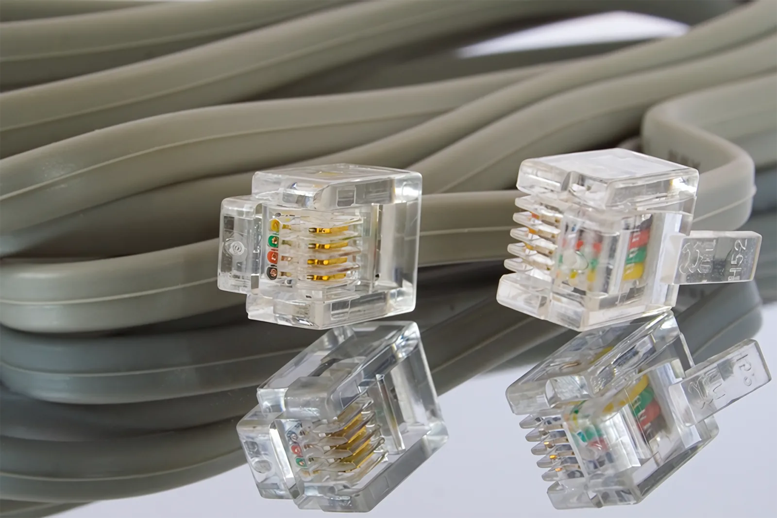
The quickest way to wreck a good industrial network is to ignore what’s happening a few centimeters from your injection-molding machines. You can have flawless switches, carefully segmented VLANs, and a shiny dashboard in the control room—but if the cabling running past hot barrels, vibrating platens, and noisy drives is unreliable, you’ll still be chasing intermittent faults, frozen HMIs, and “ghost” alarms that never show up when maintenance is watching.
In most plants, the critical path for production data isn’t the fiber uplink to the data center. It’s the last 10–30 meters of copper connecting injection-molded equipment to PLCs, robots, vision systems, and MES gateways. That’s where noise, heat, and mechanical abuse turn a theoretically robust design into a source of scrap and downtime.
Why the Network Starts at the Mold, Not the Server Room
Around injection-molding machines, the network is carrying far more than simple status bits. You’re pushing cycle times, cavity pressure curves, material traceability, energy usage, and fault histories. All of that moves as packets across a physical cable that’s often sharing space with heater circuits, hydraulic power units, and variable frequency drives.
Because of that, “good enough” office cabling practices don’t hold up. Each connection near the press has to be treated as production-critical infrastructure. That usually means choosing industrial-rated Ethernet (or fiber where it makes sense), shielding where needed, and designing routes so they stay clear of high-current conductors and moving mechanical parts. It’s also where many teams lean on specialized cabling solutions partners who understand how to route, terminate, and protect cables in harsh environments instead of treating it as generic low-voltage work.
If you’ve ever had a mold change bring a machine back in a “weird state” with missing I/O or a robot that loses its position occasionally, there’s a good chance the root cause lived in this zone. It’s not that the PLC or network switch suddenly became unreliable; it’s that a connector took a tiny hit, a cable got re-bent beyond its rating, or a run migrated a bit too close to a motor lead after the last maintenance job.
Environmental Hazards Around Injection-Molded Equipment
Injection-molding machines are compact bundles of electromagnetic trouble. You’ve got barrel heaters cycling, high-current clamp motors, VFD-driven pumps, and often nearby auxiliary machines like dryers and chillers. All of these can inject electrical noise into nearby conductors. Guidance from Cisco on industrial Ethernet and PoE emphasizes that you should avoid running Ethernet cables near high-voltage lines or strong EMI sources, and that shielded, industrial-grade cables are crucial in these environments for reliable data transmission. Cisco’s industrial PoE recommendations highlight how cable quality, shielding, and routing directly affect performance in noisy areas.
Near molding machines, this isn’t an abstract risk. EMI shows up as CRC errors, random disconnections, or jitter on time-sensitive protocols. When those packets are carrying things like mold safety interlocks or robot handshakes, small glitches translate into aborted cycles, unexpected stops, or conservative safety fallbacks that kill throughput. Choosing the right cable category is only part of the story; you also need the right shielding type, correct bonding at both ends, and consistent separation from power.
Then there’s mechanical and environmental stress. Cables might be exposed to high ambient temperatures, oil mist, plastic dust, and constant vibration. A run that looks fine on day one can gradually loosen in the connector, flatten where it passes under a cover, or crack at repeated bend points. In molding cells, it’s worth being almost obsessive about strain relief, bend radius, and where cables pass near doors, guards, and mold-change paths. Every time a crane or cart comes through, your cabling is at risk unless it’s either protected or completely out of the way.
Designing the Physical Network Around the Press
A lot of industrial network diagrams start from the core switch and work outward. Around injection-molded equipment, it’s smarter to start at the press and build back toward the network room. What devices must remain up during every cycle? Which ones can tolerate a brief retry? That dictates where local managed switches or I/O blocks live, how many links you need, and what redundancy makes sense.
In many plants, a good baseline pattern is a small industrial switch mounted in or near each machine’s control cabinet, with very short, well-protected patch leads to the PLC, HMI, and critical I/O, and then a slightly longer home-run back to the cell or area switch. That keeps the most sensitive connections in the best-protected location. From there, you can take advantage of standard control-system zoning guidance—NIST’s ICS security recommendations, for example, emphasize clear separation between control networks and other plant or corporate networks to preserve both reliability and security. NIST SP 800-82 on industrial control system security discusses architectures that isolate control assets while still allowing monitored, well-defined data flow.
Redundancy also has to be grounded in physical reality. Ring topologies, redundant uplinks, and rapid spanning-tree configurations look great on a slide, but they don’t compensate for a cable that’s repeatedly pinched in a cabinet door. If you’re adding a second path, make sure it’s truly diverse—physically separated, routed through different trays, and ideally not subjected to the same mechanical or thermal stress. Otherwise, both “redundant” cables will fail for the same reasons, just at different times.
Finally, don’t overlook documentation and standards. Around molding equipment, it’s easy to end up with one-off fixes: a quick patch-over for a vision camera here, a last-minute sensor add there. Over time that creates a tangle that no one wants to touch. Standardizing colors for network vs. control vs. power cables, labeling every run at both ends, and keeping an up-to-date network map specifically for each molding cell makes troubleshooting much faster. When a press is down and quality is on the phone, you don’t want to be guessing which unmarked cable goes to the cavity pressure sensor.
Protecting Cabling So It Survives the Real World
Even the best-designed network will fail if the cabling layout doesn’t match how the cell is actually used. Injection molding is dynamic: molds are changed, robots are re-taught, conveyors move, and temporary equipment appears during trials. The physical network has to be designed with that motion in mind.
Start with separation. Network and control cables should not share conduits or trays with heater circuits, motor feeds, or welders. Where they must cross, keep the crossing short and at right angles, and use shielding and metallic conduit where practical. This isn’t perfectionism—it’s a way to prevent the “mystery” failures that only show up during certain parts of the cycle, like clamp movement or screw recovery. In a molding area with multiple presses, it’s often worth dedicating a tray or ladder just for low-voltage networking, then enforcing that through work instructions.
Next, think about serviceability. Cabling should be protected, but also accessible without dismantling half the cell. If technicians have to fight through guards and panels to get to terminations, they’re more likely to improvise, run cables along the quickest path, or leave strain relief undone during a rushed restart. Using pre-terminated industrial connectors, modular patch panels in the machine cabinet, and clearly marked junction points between fixed and moving parts reduces that pressure. It also makes it easier to swap a known-good segment for testing instead of guessing whether the failure is in the switch, the device, or the cable.
Finally, test and re-test at the physical layer. Certifying links during installation is good; re-verifying after major changes is better. Whenever a new mold is introduced, a robot is added, or a cell is reconfigured, schedule a quick check of the cables that pass near the work area. It’s surprising how often an intermittent network issue gets traced back to a cable that was “just nudged out of the way” during a mechanical job.
Turning Cabling Reliability Into Production Results
All of this effort only matters if it moves the needle on production. The good news is that reliable cabling around injection-molded equipment shows up in metrics you already care about: downtime, scrap, and labor hours.
Think about unplanned stops. A few seconds lost to a network retry doesn’t sound serious until you multiply it by thousands of cycles per shift. Add a couple of full machine stops per week while maintenance hunts for a “PLC issue” that turns out to be a flaky connector, and suddenly you’re losing meaningful capacity. When the physical network is solid, alarms are clearer and easier to reproduce; you’re not chasing phantoms caused by dropped packets.
Scrap follows a similar pattern. Modern molding operations depend on data: cavity pressure traces for each shot, material lot tracking, and machine condition monitoring. If those data streams are intermittently missing or corrupted because of marginal cabling, you either have to scrap product to stay safe or, worse, risk bad parts escaping. A stable network means you can trust your traceability and quality analytics instead of adding manual checks as a safety blanket.
To turn this into a routine, bake cabling checks into processes you already run. When a new cell is commissioned, treat network cabling validation as part of the production sign-off, not just an IT step. When preventive maintenance is scheduled on a press, include a quick visual and physical inspection of the network runs in and around the machine: look for crushed jackets, tight bends near moving joints, and connectors that show signs of strain. When you plan capital upgrades—like adding robots, vision systems, or energy meters—include time and budget to adjust cable routes rather than layering new runs on top of old compromises.
Conclusion
If you treat the cabling around your injection-molded equipment with the same seriousness as the machines themselves, your industrial network becomes stable enough to trust with the real-time data and automation your plant depends on.


