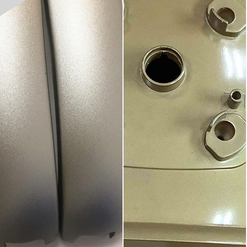
Have you ever wondered how intricate and complex features are seamlessly molded into plastic parts? The answer lies in the fascinating world of diapositives pour moules d'injection. These specialized components are the unsung heroes behind creating undercuts, threads, and other intricate details in pièces moulées.
En moulage par injection, slides play a pivotal role in achieving what might seem impossible – producing complex parts without needing multiple molding steps. They move in and out of the cavité du moule precisely, coordinating the formation of the desired shape.
Speaking of which, understanding the different slide actions and components of injection mold slides is essential for achieving precision and consistency in the injection molding process. In this article, we will delve into the inner workings of an injection mold slide, unfolding its importance and explaining how to design it effectively.
Components of the Slide System
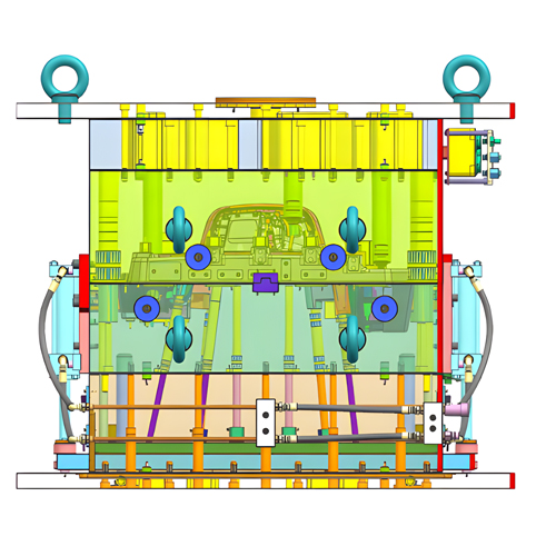
Les slide mold system comprises several key components, each serving a specific purpose in the injection molding process:
Guide Pin
Les goupille de guidage is a critical element of the slide mold. It is used to locate the core and side of the mold cavity, facilitating smooth and easy movement within the mold system. Additionally, the guide pin plays a crucial role in supporting the weight of the mold.
In cases where inserts are used, the guide pin prevents their displacement. To ensure proper functionality, the guide pin should be positioned between 15 and 25 mm above the product. Furthermore, the slider guide pin, located 10 to 15 mm below the mold guide pin, guides the movement of the slide.
Slide Body
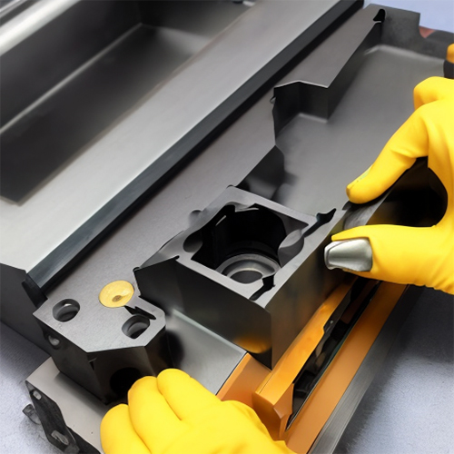
Les slide body is an integral part of the slide system, housing the components necessary for the sliding mechanism. It provides structural support and ensures the coordinated movement of other components.
Wear Plate
Wear plates are designed to minimize friction and wear between moving parts of the slider system. They help extend the lifespan of the components and ensure smooth operation.
Press Block
Les press block plays a role in exerting the necessary pressure and force for the proper functioning of the slider. It works in tandem with other components to facilitate the slide’s motion.
Types of Guide Pins
The choice of guide pin type depends on the product and mold’s specific requirements. Two key differences in guide pin types are their height above the slide and the lock mechanisms. Let’s explore these types:
- Thin Mold Plates or Clamped Plates: These provide good stability and a surface matte finish.
- For 2 or 3 Part Plates with Thick Plates and Large Mold Cavity: These guide pins feature a length-to-diameter ratio of 1.5 or higher. They work well for thin seperable mold plates while offering good stability and a matte finish.
- For 2 or 3 Part Plates with Thick Plates and Large Mold Cavity: These guide pins also feature a length-to-diameter ratio of 1.5 or higher. However, this type may exhibit poor stability and processability.
The Role of the Guide Block
The guide block, sometimes called a slider, complements the guide pin’s function. Working together, they facilitate both vertical and horizontal motion within the system.
The guide block exerts a force on the guide pin, ensuring it remains in place even under high mold pressure. Additionally, the guide block guides the motion of the guide pin, allowing for precise and controlled movement.
Understanding these mechanisms is vital for achieving efficient and reliable injection molding processes. Each component plays a unique role in ensuring the successful production of high-quality molded parts.
Step-by-Step Guide to Designing an Injection Mold Slide
Designing an effective injection molding slider is a crucial part of the mold creation process. These slides play a pivotal role in enabling the production of complex parts with undercuts, threads, and intricate features. To help you navigate this process, here’s a step-by-step guide for designing an injection slide mold:
1. Initial Design Considerations
Begin by reviewing the part design to identify features that necessitate the use of slide molds. These features could include undercuts, threads, or other complex shapes. The part design will determine the type and number of slides required.
2. Material Selection
Choose the appropriate material for the slides. It’s essential to select a material that is compatible with both the mold material and the specific molding process. Common materials for slides include tool steel, aluminum, and beryllium copper.
3. Determining Slide Type and Number
Based on the part design, decide on the type of slide needed. The choice of slide type depends on the specific feature to be created, such as undercuts or threads. Additionally, determine the number of slides required, which will depend on the complexity of the part and the number of features to be produced.
4. Calculating Slide Dimensions
Accurately calculate the dimensions of the slides. These dimensions ensure proper movement and clearance within the mold cavity. The calculations will be influenced by the part design and the type and number of slides used.
5. Draft Angle Considerations
Incorporate draft angles into the slide mold design. Draft angles are essential to prevent damage to the part during ejection. Be sure to consider both the angle de dépouille of the part and the slide in your design.
6. Interlocking Features
Include interlocking features in your slide design to prevent any undesired movement during the molding process. These interlocking features help maintain the integrity of the slides and ensure accurate part production.
7. Designing for Manufacturability
Optimize your slide design for ease of manufacturing, assembly, and maintenance. This optimization reduces costs and minimizes downtime. Remember the specific manufacturing process and equipment available during the design phase.
Common Mistakes to Avoid in Injection Mold Slide Design
While designing slides for injection molds, it’s essential to be mindful of common pitfalls that can hinder the production of high-quality parts. By avoiding these mistakes, you’ll enhance the efficiency and effectiveness of your slide mold design. Let’s delve into these common errors in more detail:
Neglecting Draft Angle Considerations
One of the most fundamental errors is failing to account for the draft angle of both the part and the slide. The draft angle is crucial in preventing damage to the part during ejection. Without adequate draft angles, parts may get stuck or damaged during the release process. Always consider and incorporate appropriate draft angles into your slide design.
Inappropriate Material Selection
Selecting the wrong materials for your slides can be a costly mistake. The chosen material should be compatible with the mold material and the specific molding process.
Using incompatible materials may lead to premature wear and tear of the slides, reducing their lifespan and impacting part quality. Common materials for slides include durable options like tool steel, aluminum, and beryllium copper. Make an informed choice based on your project’s requirements.
Overly Complex Slide Designs
Simplicity is often the key to successful slide design. Creating overly complex slides can result in difficulties during manufacturing, assembly, and maintenance. Complex designs may also increase costs and lead to unnecessary downtime. To avoid this mistake, prioritize straightforward and effective slide designs that align with the specific features required for your parts.
Omitting Interlocking Features
Failure to include interlocking features in your slide design can lead to unwanted movement during the molding process. These features are very important for keeping the slides stable and in place, especially when they are under pressure. Incorporating interlocking mechanisms ensures that the slides function as intended, preventing errors and defects in the final parts.
Injection Molding Slide and Lifter: How Are They Different?
Are you confused about how an injection mold slide differs from a lifter? Let’s delve further into the specific differences between mold lifters and sliders to gain a comprehensive understanding of their unique applications and mechanical mechanisms.
| Difference | Lifter | Slider |
| Meaning | A mechanism used to shape barbs within the product, suitable for simple barbs. | A mold component that can slide in the mold opening direction or at an angle to it. |
| Application | Used for electrical processing equipment for copper-based and iron-based powder products, among others. | Widely used in various fields, including CNC machines, automotive, and medical equipment. |
| Mechanical Mechanism | Employs mechanisms like pushing block ejecting, molding parts ejecting, and air pressure ejecting. | Typically, it operates by sliding the core to eject the molded part. |
Summing Up: Deciding When an Injection Mold Slider Is Crucial!
If you’re unsure if injection mold slides are the optimal choice for your specific application, you can consider several key factors, including:
Taille de la pièce : Evaluate the size of the part you intend to produce. Sliders are typically best suited for smaller parts as they require the mold to open and close for the slider to function effectively.
Sélection des matériaux : Consider the material you plan to mold. Injection molding slides are not typically employed for softer materials, as they may lead to issues like sticking and uneven cooling.
Production Volume: Think about the production volume of your part. Sliders can experience wear and tear, especially during long production runs, and incur significant costs. For larger products, it may be prudent to maintain spare sliders to mitigate the impact of wear and tear on your production schedule.
By considering these factors carefully, you can decide if an injection mold slider is suitable for your specific needs.
Still have questions? Feel free to connect with our professional team of manufacturers at Prototool.com.

