जबकि इंजेक्शन मोल्ड उपकरण डिज़ाइन और निर्माण करना कठिन होते हैं, लेकिन उनकी मूल अवधारणाएँ समझने में सरल हैं। साँचे में दो सतहें होती हैं, जिनमें से एक पर एक गुहा और कोर वह सेट जिसमें प्लास्टिक इंजेक्ट किया जाता है। प्लास्टिक – जैसा कि नाम से ही स्पष्ट है, यह स्प्रू के माध्यम से मोल्ड में प्रवेश करता है, जो रनर प्लास्टिक को आपूर्ति करता है – गेट के जरिए मोल्ड की गुहा में प्रवेश करता है। इंजेक्शन मोल्डिंग गेट प्लास्टिक के कैविटी/कोर में प्रवेश का वास्तविक बिंदु है और इस प्रकार यह मोल्ड की सफलता या विफलता तय कर सकता है। यदि मोल्ड बहुत छोटा होगा तो यह भर नहीं पाएगा; यदि यह बहुत बड़ा होगा तो प्लास्टिक को काटना बहुत कठिन होगा।.
इस गाइड में, हम इंजेक्शन मोल्डिंग गेट से संबंधित सभी बातों पर चर्चा करेंगे। और जानने के लिए पढ़ते रहें!
इंजेक्शन मोल्डिंग गेट क्या है?
इंजेक्शन मोल्डिंग में, गेट एक छोटा, रणनीतिक रूप से रखा गया उद्घाटन होता है, जिसका उपयोग प्लास्टिक पिघल के मोल्ड कक्ष में प्रवाह को नियंत्रित करने के लिए किया जाता है। उचित इंजेक्शन मोल्डिंग गेट का उपयोग आपके मोल्डेड घटकों की गुणवत्ता की गारंटी दे सकता है।.
इंजेक्शन मोल्डिंग प्रक्रिया में पिघले हुए प्लास्टिक की मात्रा, दबाव और तापमान गेट का प्रकार, स्थिति, आयाम, सामग्री और मोल्ड का प्रकार जैसे पैरामीटर से प्रभावित होते हैं।. इंजेक्शन मोल्ड गेट डिज़ाइन कई क्षेत्रों में जटिल प्लास्टिक घटक बनाने के लिए इसका उपयोग किया जाता है।.
इंजेक्शन मोल्डिंग गेट्स के मूल सिद्धांत
गेट्स को मोल्ड विभाजन रेखाओं के साथ या कैविटी में रणनीतिक रूप से रखा जा सकता है। ये छेद प्रवाह नियंत्रण में सहायता के लिए संकरे या चौड़े, संकीर्ण या स्थिर व्यास वाले हो सकते हैं। गेट्स की गहराई इसलिए होती है क्योंकि वे मोल्ड से बाहर की ओर उभरे होते हैं। कैविटी में गेट्स की संख्या और उनकी जटिलता से मोल्ड की लागत प्रभावित होती है। चक्र समय और भागों की दृश्य उपस्थिति भी गेट्स से प्रभावित होती है।.
अधिकांश पिघला हुआ प्लास्टिक सामग्री इंजेक्शन मोल्डिंग के दौरान मोल्ड गुहा के भीतर ठंडी होकर ठोस हो जाती है और पूर्ण घटक का निर्माण करती है। कुछ प्लास्टिक गेट पर कठोर हो जाता है और भाग की सतह से उभर आता है। अतिरिक्त सामग्री को हटाने की प्रक्रिया, जिसे डी-गेटिंग कहते हैं, भाग की गुणवत्ता के लिए अत्यंत महत्वपूर्ण है और इसे मैन्युअल या स्वचालित रूप से किया जा सकता है।.
गेट ट्रिमिंग: मैनुअल बनाम स्वचालित
जैसे विनिर्माण सेवा प्रदाताओं द्वारा उपयोग की जाने वाली उन्नत तकनीक के साथ प्रोटो टूल, जब गेट स्वचालित रूप से ट्रिम हो जाते हैं, तो मानवीय हस्तक्षेप अनावश्यक हो जाता है। इसके बजाय, जैसे ही भाग हटाया जाता है, रनर से अतिरिक्त गेट सामग्री काटे जाने से अलग हो जाती है।.
मैनुअल या स्वचालित ट्रिमिंग के लिए विभिन्न प्रकार के गेट बनाए जाते हैं, और जबकि स्वचालित रूप से ट्रिम किए गए गेट सबसे अच्छा विकल्प प्रतीत हो सकते हैं, वे अनिवार्य रूप से सर्वश्रेष्ठ नहीं होते। आइए इन दोनों गेटों में शामिल अन्य प्रकारों/डिज़ाइनों के बारे में बात करें:
मैन्युअली ट्रिम्ड गेट प्रकार:
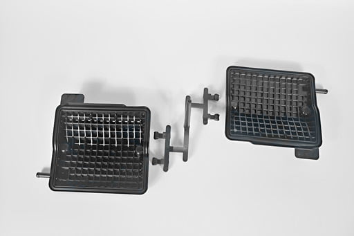
एज गेट
सपाट घटकों के लिए किनारे वाले या पारंपरिक गेट को प्राथमिकता दी जाती है। ऐसा क्यों है? क्योंकि सबसे आम और सरल इंजेक्शन मोल्ड गेट डिज़ाइन किनारे वाला गेट है। इसे अक्सर वर्कपीस के किनारे पर रखा जाता है, जिससे नाम के अनुसार सीमा रेखा पर एक दिखाई देने वाला निशान बनता है। इसका क्रॉस-सेक्शनल क्षेत्रफल बड़ा होता है, जिससे पिघला हुआ प्लास्टिक कैविटी में प्रवाहित हो सकता है।.
डायरेक्ट या स्प्रू गेट्स:
बड़े, बेलनाकार टुकड़ों में प्रत्यक्ष या स्प्रू गेट लगाए जाते हैं। इंजेक्शन मोल्डिंग में सबसे सामान्य गेट डिज़ाइनों में से एक प्रत्यक्ष/स्प्रू प्रकार है। बड़ी मात्रा में प्लास्टिक को जल्दी से इंजेक्ट किया जा सकता है। स्प्रू, जो सीधे मोल्ड कक्ष में चलता है और पिघल जाता है। अधिकांश मामलों में, कम इंजेक्शन दबाव और छोटा खिलाने का समय की आवश्यकता है। न्यूनतम डिज़ाइन प्रयास के साथ प्रत्यक्ष गेट के आसपास उच्च तन्यता तनाव उपलब्ध है।.
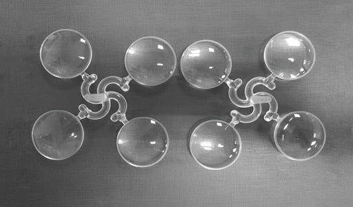
डिस्क या डायाफ्राम गेट्स:
इन गेट्स का उपयोग ऐसे गोलाकार या बेलनाकार तत्वों के साथ किया जाता है जिन्हें समकेंद्रता की आवश्यकता होती है। इसके अलावा, इंजेक्शन मोल्डिंग गेट को हटाना अक्सर मुश्किल और काटने में महंगा होता है। चूंकि ये दोनों गेट के नीचे से संकीर्ण होते हुए निकलते हैं, इसलिए डायाफ्राम गेट और स्प्रू गेट एक जैसे दिखते हैं। इन गेट्स का उपयोग आमतौर पर कोणीय आकार के मोल्डेड पुर्जों के साथ किया जाता है। हालाँकि इंजेक्शन मोल्डिंग प्रक्रिया का तापमान, गति और दबाव निकाले गए घटक की गुणवत्ता को प्रभावित कर सकते हैं, डायफ्राम गेट प्रभावी रूप से मोल्डेड भागों पर वेल्ड लाइनों और लिपटे हुए आकारों के उत्पादन को कम करता है।.
प्रशंसक द्वार:
उनके पास एक बड़े एपर्चर के साथ अलग-अलग मोटाइयाँ. ये बड़े घटकों और नाजुक साँचे के खंडों को तेजी से भरने में सक्षम बनाते हैं। फैन गेट्स, जैसा कि नाम से ही स्पष्ट है, पंखे के आकार के होते हैं। इन गेट्स द्वारा बनाए गए चौड़े उद्घाटन के माध्यम से साँचा गुहा में प्रवेश कर सकता है। ये गेट्स धीरे-धीरे चौड़े होते जाते हैं और रनर से साँचे की गुहा की दिशा तक पंखे का आकार बनाते हुए मोटाई में समान रहते हैं। इन्हें अक्सर बड़े हिस्सों में एक समान प्रवाह सुनिश्चित करने के लिए उपयोग किया जाता है।.
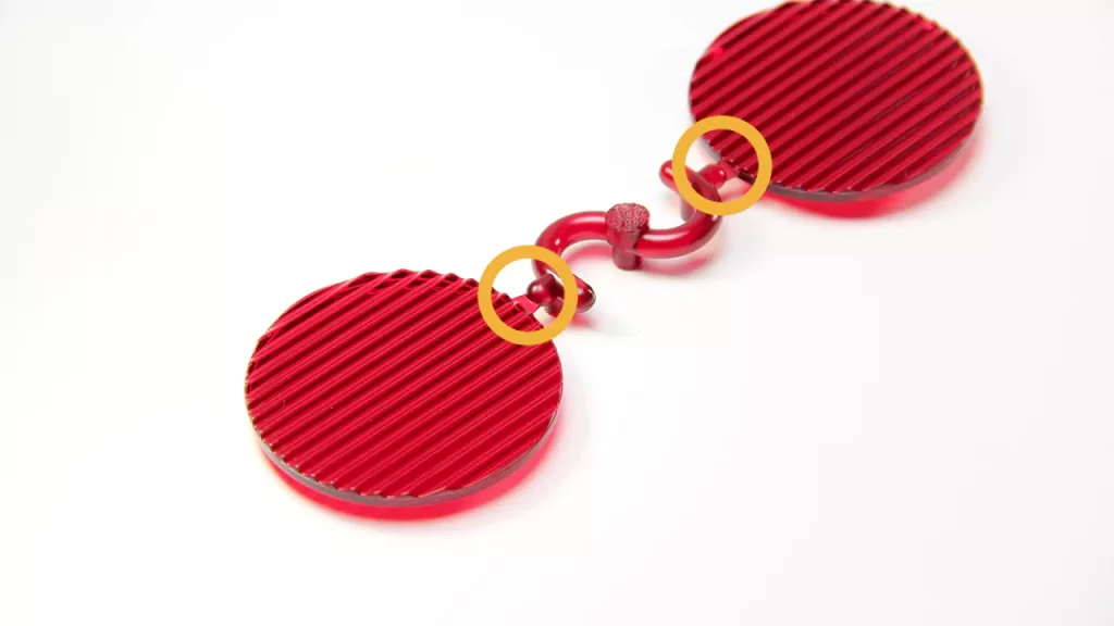
काजू गेट्स:
काजू गेट का आकार एक ट्री नट जैसा होता है। निर्माता इस प्रकार के गेट का उपयोग उन उत्पादों के लिए करते हैं जिन्हें गेट हटाने के दौरान विकृत हो सकता है। काजू गेट की वक्राकार प्रकृति मोल्डेड भागों को बिना नुकसान या विकृति के निकालना कठिन बना देती है।.
अतिरिक्त गेट प्रकार/गुणधर्म:
- गेट का आयताकार क्रॉस-सेक्शन होता है जिसे घटक और रनर के बीच संकरा किया जा सकता है।.
- एक स्प्रू सामग्री को गुहा में निर्देशित करता है और तेजी से खिलाता है।.
- टैब गेट का उपयोग न्यूनतम शीयर तनाव वाले पतले, समतल भागों के लिए किया जाता है। ये विकृतियाँ टैब-जैसी संरचना द्वारा गेट क्षेत्र तक सीमित रहती हैं।.
- रिंग गेट सामग्री को स्वतंत्र रूप से प्रवाहित होने देते हैं, इससे पहले कि वह सांचें को भरने के लिए एक समरूप, नली-नुमा विस्तार में प्रवेश करे।.
- स्पोक् गेट्स गोलाकार गेट्स होते हैं जिनके केंद्र में एक क्रॉस होता है। इन्हें ट्यूब-आकार के टुकड़े बनाने के लिए उपयोग किया जाता है, लेकिन सटीक समकेन्द्रता प्राप्त करना कठिन होता है।.
स्वचालित रूप से ट्रिम किए गए गेट प्रकार:
हॉट टिप गेट्सये गेट शंकु या गोलाकार आकृतियों को साँचे की गुहा में एकसमान प्रवाह के साथ समायोजित कर सकते हैं। इन्हें हॉट रनर सिस्टम में उपयोग किया जाता है, जो प्लास्टिक को पिघला हुआ बनाए रखते हैं जब तक कि वह गुहा में प्रवेश न कर जाए।.
पिन गेट्स: ये गेट्स के साथ उपयोग किए जाते हैं तेज़-बहने वाले रेज़िन और जहाँ किसी भाग की दृश्य उपस्थिति महत्वपूर्ण होती है। इन्हें अक्सर उन वस्तुओं पर उपयोग किया जाता है जो विभाजन रेखा के दोनों ओर नहीं रह सकतीं। पिन गेट अक्सर मोल्ड के बी-साइड पर, के पास स्थित होते हैं। निकालने वाले पिन. एक पिन गेट तीन प्लेट मोल्डों के लिए उपयुक्त है, जिसमें रनर चैनल एक अलग रनर प्लेट पर स्थित होता है; मोल्ड फ्लो कई तरीकों से विभाजित होता है, और विभिन्न गेट स्थानों से कैविटी तक जाता है। चूंकि गेट का बिंदु बहुत छोटा होता है, इंजेक्शन मोल्ड खोलते समय इसे काटकर हटाया जा सकता है। बड़े रनर के कारण इसकी स्क्रैप दर अधिक होती है, जो एक कमी है।.
पनडुब्बी या सब गेट्स: इन गेटों में एक संकीर्ण होता हुआ चैनल होता है, जो गेट दोषों को छिपाने में मदद कर सकता है। इन छिद्रों को टनल गेट के नाम से भी जाना जाता है। सबमरीन या टनल इंजेक्शन मोल्डिंग गेट आमतौर पर के नीचे स्थित होता है। मोल्ड की विभेदन रेखा, जिससे घटक निष्कासन के दौरान स्वचालित छंटाई संभव होती है। इसमें विभाजन रेखा के नीचे से एक पतली नली के माध्यम से गुहा को भरना शामिल है, जो भाग रेखा के पास गुहा से जुड़ती है। इसी तरह, ड्राफ्ट कोण तैयार प्लास्टिक के टुकड़ों को बिना टूटे बाहर निकालना आसान बनाता है।.
इंजेक्शन मोल्डिंग गेट डिज़ाइन पर विचार:
· द्वार की स्थिति
कुछ गेट्स की जटिल स्थिति के कारण कुछ क्षेत्रों को दूसरों की तुलना में अलग करना अधिक चुनौतीपूर्ण होता है। इसी तरह, विशेष गेट्स को बंद करने के क्रम के कारण ढाले गए टुकड़ों में विकृतियाँ और रेखाएँ उत्पन्न हो सकती हैं। इसलिए, आपको अपने इंजेक्शन मोल्डिंग डिज़ाइन में गेट्स के स्थान पर बारीकी से ध्यान देना चाहिए।.
· गेट का आकार
इंजेक्शन मोल्डिंग करते समय, गेट का आकार इतना बड़ा होना चाहिए कि जब भी मोल्ड मशीन से गुजरे, तब सही शीयरिंग हो सके। गेट के आयाम ऐसे होने चाहिए कि वे मोल्ड को सही ढंग से भरने की अनुमति दें। छोटे क्रॉस-सेक्शन वाले गेट्स में शीयर हीटिंग दरें अधिक होती हैं। हालांकि, यदि वे बहुत छोटे या बहुत बड़े हों, तो वे अनजाने में फ्लो दबाव बढ़ा सकते हैं। इसलिए, यदि आप सर्वोत्तम परिणाम चाहते हैं, तो आपको उपयुक्त आकार के गेट्स का उपयोग करना चाहिए।.
· घटक का आकार और सतह
विभिन्न आकृतियों वाले घटकों को मोल्ड करते समय एक निश्चित गेट डिज़ाइन चुनना और एक विशिष्ट फिनिश प्राप्त करने के लिए काम करना अनुशंसित है। उदाहरण के लिए, काजू गेट डिज़ाइन छोटे हिस्सों पर काम करने के लिए उत्तम है क्योंकि यह पूरे भाग पर चिकनी और एकसमान सतह फिनिश प्रदान करता है।.
परिणामस्वरूप, आपको अपने घटकों और प्राप्त करना चाहने वाली सतह फिनिश के लिए सर्वोत्तम गेट स्थापित करना होगा। जटिल डिज़ाइनों पर काम करते समय, आप अंडरकट जैसी विशेषताओं पर भी विचार करना चाह सकते हैं, जो पूर्ण प्लास्टिक घटकों के निर्बाध निष्कासन में बाधा डाल सकती हैं।.
विचार करने योग्य अतिरिक्त कारक: इंजेक्शन की दरें और समय
जब प्लास्टिक को गेट के माध्यम से उच्च गति से इंजेक्ट किया जाता है, तो घर्षण के कारण तापमान बढ़ सकता है, और यदि पर्याप्त अतिरिक्त गर्मी हो, तो प्लास्टिक की आणविक संरचना प्रभावित हो सकती है। हालांकि, क्षरण को रोकने के लिए इंजेक्शन गति धीमी करने पर वेल्ड लाइनें उत्पन्न हो सकती हैं और वस्तु की यांत्रिक मजबूती में कमी आ सकती है। इसके अतिरिक्त, धीमी चक्र समय के कारण प्रति घंटे कम भाग उत्पादित होते हैं, जिससे प्रसंस्करण लागत बढ़ जाती है।.
इंजेक्शन मोल्डर्स इंजेक्शन गति और गेट आकार के इष्टतम स्तर की पहचान करने के लिए सापेक्ष चिपचिपापन बनाम शियर दर वक्र का उपयोग करें। ऐसा इसलिए है क्योंकि यह निर्धारित करने वाला एकमात्र कारक गेट आकार नहीं है कि इंजेक्शन गति को बढ़ाया जाना चाहिए या घटाया जाना चाहिए।.
निष्कर्ष:
इंजेक्शन मोल्ड गेट डिज़ाइन प्लास्टिक मोल्ड की गुणवत्ता और उत्पादकता सुनिश्चित करने में महत्वपूर्ण है। उपयुक्त गेट डिज़ाइन उत्कृष्ट मोल्ड और दोषपूर्ण मोल्ड के बीच का अंतर तय कर सकता है। उचित इंजेक्शन मोल्डिंग गेट डिज़ाइन उत्पादन लागत कम करने और चक्र समय को अनुकूलित करने में सहायक होता है।.
अधिक जानकारी और पूछताछ के लिए, कृपया Prototool पर हमसे संपर्क करें।.


