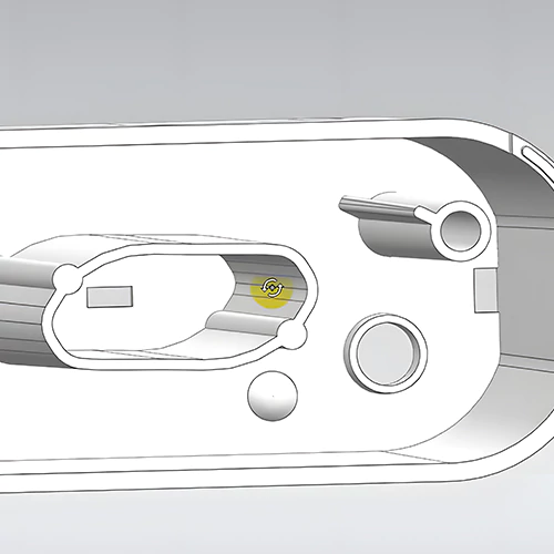
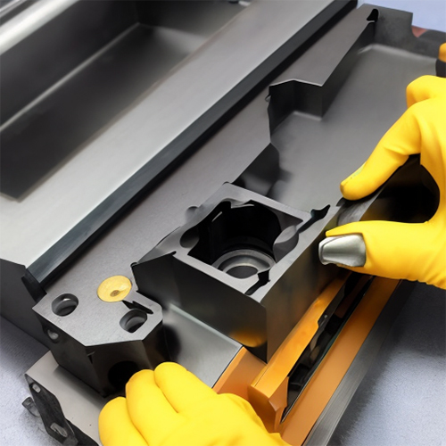
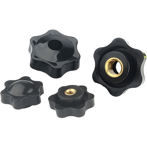
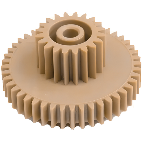
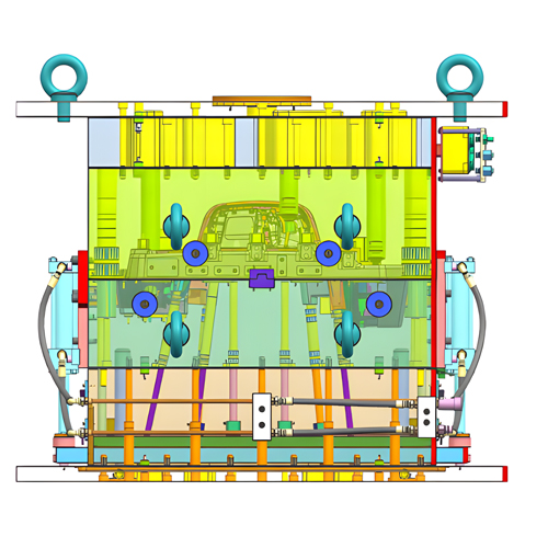
While injection mold tools are difficult to design and manufacture, their essential concepts are simple to grasp. The mold comprises two faces, one of which has a cavity and core set into which the plastic is injected. The plastic – which, as the name suggests, is injected into the mold via a sprue that feeds the runner plastic – enters the mold’s cavity via the gate. The injection molding gate is the literal entrance point for plastic into a cavity/core and, as such, can make or break a mold. If the mold is too tiny, it will not fill; if it is too huge, the plastic will be too difficult to shear.
In this guide, we will talk about everything related to an injection molding gate. Keep reading to learn more!
What is Injection Molding Gate?
In injection molding, a gate is a small, strategically placed opening used to regulate the flow of plastic melt into the mold chamber. Using the proper injection molding gate can guarantee the quality of your molded components.
The amount, pressure, and temperature of the molten plastic in the injection molding process are affected by parameters such as gate type, position, dimensions, material, and mold type. Injection mold gate design is used in several sectors to create intricate plastic components.
The Fundamentals of Injection Molding Gates
Gates can be placed along mold separation lines or strategically throughout the cavity. These holes can be broad or narrow, with tapered or constant diameters to aid flow control. Gates have depth because they protrude from the mold. Mold costs are affected by the number of gates in a cavity and their complexity. Cycle times and the visual appearance of parts are also affected by gates.
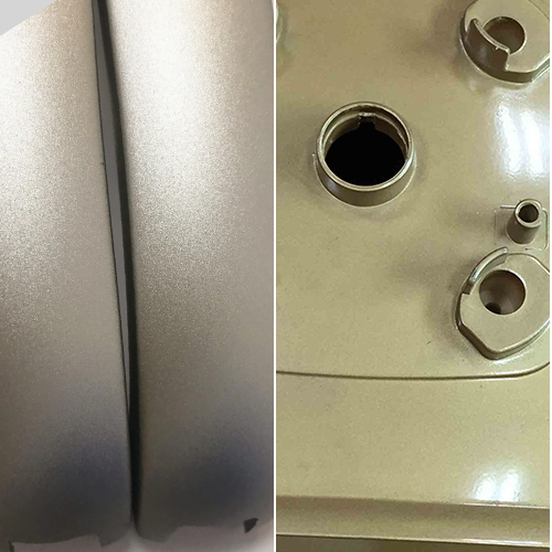
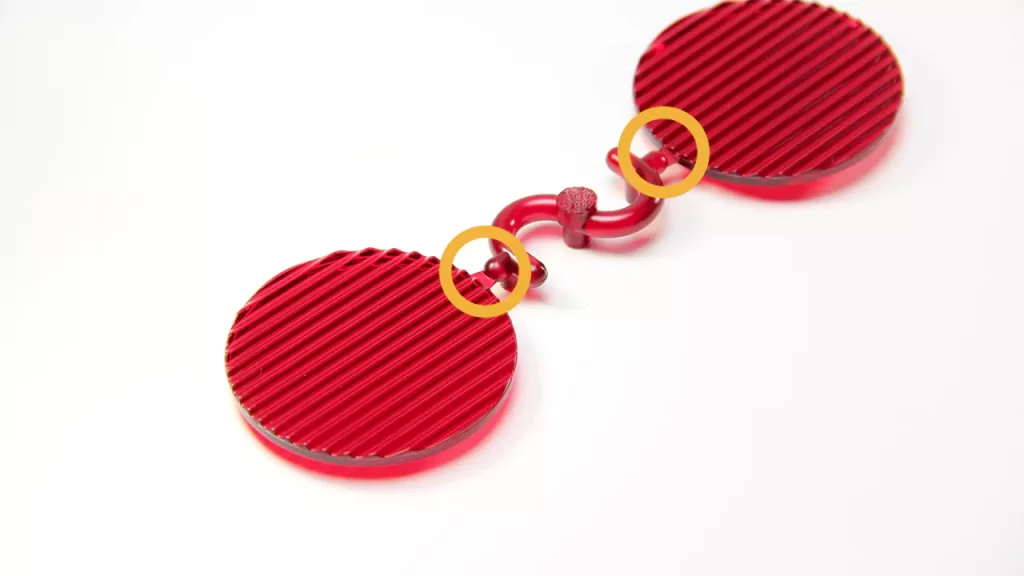
Most molten plastic material cools and solidifies inside the mold cavity during injection molding to form the completed component. Some plastic hardens at the gate and protrudes from the part’s surface. De-gating, the act of removing excess material, is critical for part quality and can be done manually or automatically.
Gate Trimming: Manual vs. Automatic
With the advanced technology used by manufacturing service providers like Prototool, human interaction is unnecessary when gates are automatically trimmed. Instead, as the part is removed, extra gate material is sheared from the runner.
Different types of gates are built for manual or automatic trimming, and while automatically trimmed gates may appear to be the best option, they aren’t necessarily. Let’s talk about the further types/designs involved in both these gates:
Manually Trimmed Gate Types:
Edge Gate
For flat components, edge or conventional gates are preferred. Why is that? Because the most common and straightforward injection mold gate design is the edge gate. It is often positioned at the edge of the workpiece, forming a visible mark at the demarcating line, as the name implies. It has bigger cross-sectional areas, allowing molten plastic to flow into the cavity.
Direct or Sprue Gates:
Large, cylindrical pieces are fitted with direct or sprue gates. One of the most typical gate designs in injection molding is the direct/sprue type. Large quantities of plastic may be injected quickly into the sprue, which moves and melts directly into the mold chamber. In most cases, lower injection pressure and shorter feeding times are needed. High tensile stress in the vicinity of a direct gate is available with minimal design effort.
Disc or Diaphragm Gates:
These gates are utilized with round or cylindrical elements that require concentricity. Moreover, an injection molding gate is often difficult to remove and expensive to cut. Because they both taper out from underneath the gate, the diaphragm gate and the sprue gate appear identical. These gates are typically utilized with angular-shaped molded parts. Even though the injection molding process’s temperature, speed, and pressure might affect the quality of the ejected component, the diaphragm gate effectively reduces the production of weld lines and wrapped shapes on the molded parts.
Fan Gates:
They have a large aperture with different thicknesses. They enable the rapid filling of large components and fragile mold sections. Fan gates, as the name suggests, are shaped like fans. Mold can enter the cavity through a wide opening created by these gates. The gate gradually widens to form a fan shape from the runner to the direction of the mold cavity while remaining consistent in thickness. They are frequently utilized to create a consistent flow into huge portions.
Cashew Gates:
The cashew gate is shaped like a tree nut. Manufacturers use this gate type for products that can be disfigured during gate removal. The curved nature of the cashew gate makes it difficult to withdraw molded parts without harming or deforming them.
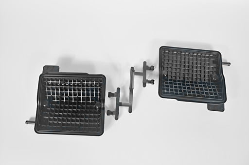
Additional Gate Types/Properties:
- The gate has a rectangular cross-section that can be tapered between the component and the runner.
- A sprue directs and swiftly feeds material into the cavity.
- Tab gates are utilized for thin, flat parts with minimal shear stresses. These strains are limited to the gate region by a tab-like structure.
- Ring gates let the material flow freely before it enters a homogeneous, tube-like extension to fill the mold.
- Spoke gates are spherical gates with a cross in the center. They’re utilized to make tube-shaped pieces, but achieving exact concentricity is difficult.
Automatically Trimmed Gate Types:
Hot Tip Gates: These gates can accommodate conical or spherical shapes with a homogeneous flow into the mold cavity. They are employed in hot runner systems, which maintain the plastic molten until it enters the cavity.
Pin Gates: These gates are used with fast-flowing resins and where the visual appearance of a part is important. They are frequently used on goods that cannot remain on both sides of the separating line. Pin gates are often located on the mold’s B-side, near the ejector pins. A pin gate is appropriate for three plate molds with the runner channel positioned on a different runner plate; the mold flow is split in numerous ways, with varied gate locations going to the cavity. Because the gate point is so small, the injection mold opening can trim it off. Because of the huge runner, it has a high scrap rate, which is a drawback.
Submarine or Sub Gates: These gates have a tapering channel, which may help conceal gate defects. These apertures are also known as tunnel gates. The submarine or tunnel injection molding gate is typically located beneath the mold parting line, allowing for automatic trimming during component ejection. It entails filling the hollow from below the dividing line using a thin tube that joins the cavity near the parting line. Similarly, the draft angle makes it easier to discharge finished plastic pieces without breaking.
Injection Molding Gate Design Considerations:
· Gate Placement
Due to the tricky location of some of the gates, it is more challenging to segregate certain areas than others. Similarly, the order in which particular gates are closed might result in malformations and lines in the molded pieces. As a result, you need to pay close attention to the location of the gates in your injection molding design.
· Gate Size
When doing injection molding, the gate size must be large enough to allow correct shearing whenever the mold goes through the machine. The gate dimensions have to be such that they permit the mold to be correctly filled. Shear heating rates are higher in gates with a smaller cross-section. However, if they are either too little or too large, they have the potential to raise the flow pressure inadvertently. Therefore, if you want the greatest outcomes, you should utilize gates of an appropriate size.
· Form and Surface of the Component
Choosing a certain gate design when molding components with various shapes and working toward a specific finish is recommended. For example, the cashew gate design is perfect for working on smaller parts because it provides a surface finish that is smooth and homogeneous over the whole part.
As a result, you need to establish the optimal gate for your components and the surface finish you want to achieve. When working with complex designs, you might also want to consider characteristics such as undercuts, which can obstruct the unobstructed expulsion of completed plastic components.
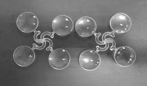
Additional Factors to Consider: Injection Rates and Times
When plastic is injected at high speeds via a gate, friction can cause temperatures to rise, and if there is sufficient additional heat, the plastic’s molecular structure could be compromised. However, if the injection speed is slowed to prevent degradation, this may result in weld lines and a reduction in the mechanical strength of the item. In addition, slower cycle times result in fewer parts produced each hour, leading to higher processing costs.
Injection molders utilize a relative viscosity vs. shear rate curve to identify the optimal level of injection speed and gate size. This is because gate size is not the only factor determining whether injection speed should be increased or decreased.
Conclusion:
Injection mold gate design is critical in assuring plastic mold quality and productivity. The appropriate gate design can mean the difference between great molds and flawed ones. The proper injection molding gate design aids in lowering production costs and optimizing cycle times.
For more details and queries, feel free to contact us at Prototool.

