Gear mold design, especially for plastic gears, differs significantly from traditional mold designs. Key parameters such as tooth thickness (the arc length between two sides of a gear tooth), module (a parameter measuring gear size), and pressure angle (the acute angle between the direction of force and direction of motion, excluding friction) require adjustments based on empirical data.
Unlike other processes, gear molds cannot be directly processed based on shrinkage rates. Professional gear and gearbox manufacturers, leveraging long-term experience and collaboration with computer software companies, have developed specialized software for calculating gear mold cavity parameters. This software can directly generate gear parameters and profiles, aiding in gear modification and enhancing tooth accuracy. Let’s delve into the intricacies of plastic gear mold design.
Cavity Design for Plastic Gear Molds
Designing the cavity for a plastic gear mold has always been a technical challenge in the mold industry, primarily due to two reasons:
1. Precision in Plastic Shrinkage Rates:
During the molding process of plastic gears, plastic granules transform into a molten state under high heat and then cool down to form solid plastic gears. The shrinkage rate of plastic during this process is a range value, making it difficult to determine precise shrinkage rates.
2. Non-linear Shrinkage Calculation for Mold Cavities:
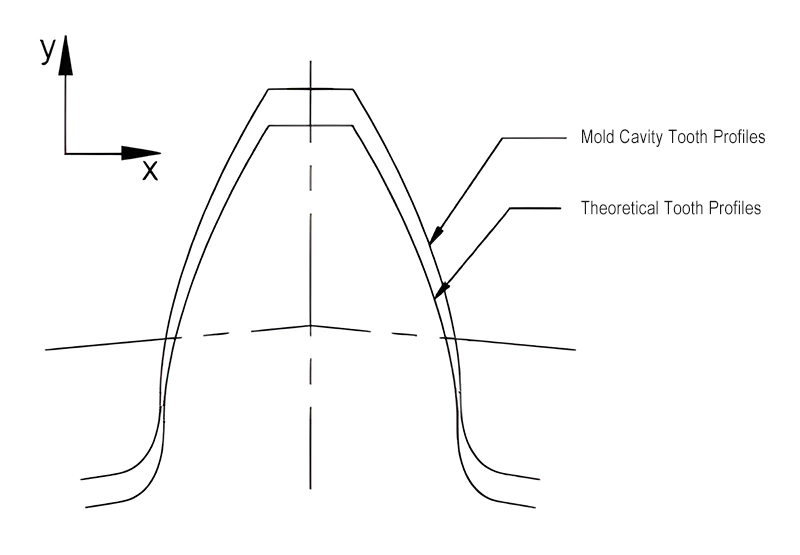
For involute small module plastic gear molds, the mold cavity essentially represents an imaginary gear. This imaginary gear differs from both shifted gears and internal gears. After shrinkage, it becomes the desired plastic gear. The shrinkage on the involute tooth profile of this imaginary gear is not uniform like the isotropic shrinkage seen in general plastic parts. On the gear plane, the shrinkage in the x and y directions is unequal, leading to non-linear shrinkage, as shown in Figure 1. This non-linearity significantly increases the complexity of designing involute plastic gear mold cavities.
The right way to design a gear mold cavity
Facing these technical challenges, using the isotropic shrinkage method for designing mold cavities often yields suboptimal results. Based on years of practical experience and precise estimation of plastic shrinkage rates, we recommend using the variable module method for theoretical design of gear mold cavities, followed by tooth profile correction to ensure accuracy and rationality of the mold cavity.
The variable module method assumes that during various processing stages, the base circle diameter, pitch circle diameter, addendum circle diameter, and dedendum circle diameter of a gear remain consistent, scaling up or down proportionally, similar to the radial dimension changes in simple sleeve-like parts. For a gear’s pitch circle, as determined by the formula d=mz, it is dependent only on the module m and the number of teeth z.
Since the number of teeth on a specific gear is constant, we can consider the change in the pitch circle diameter during processing as a change in the module. This principle implies that the space encompassed by the plastic gear mold cavity is an imaginary gear with constant number of teeth and pressure angle, with its grooves forming the cavity’s tooth profile.
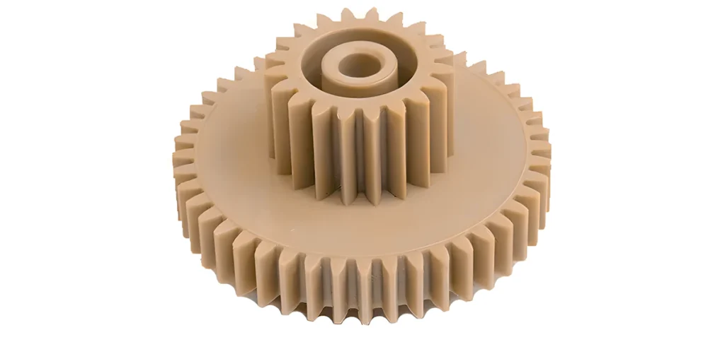
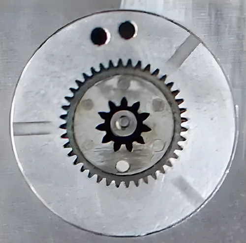
We can calculate the module of this imaginary gear using a proportional method. The formula for this calculation is m’ = (1 + η%)m. In this formula, m’ represents the module of the mold cavity tooth profile, m is the theoretical module of the designed gear, and η% is the plastic’s shrinkage rate. By substituting the module m’ into the corresponding gear calculation formula, the resulting gear represents the imaginary gear of the mold cavity. Practice has shown that the variable module method effectively addresses the challenge of non-linear shrinkage in involute tooth profiles, as demonstrated by the mold cavity product shown in Figure 2.
Gate Design for Plastic Gear Molds
In the process of molding plastic gears, the location of the gate significantly impacts the precision of the gears, especially their radial runout. The distribution form of the gate also crucially affects the overall mechanical properties of the plastic gears. When designing gates for plastic gear molds, if the gear product allows, it is recommended to use a three-point gating system. Ideally, these three points should be located on the same circular arc and evenly distributed, as shown in Figure 3.
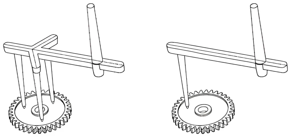
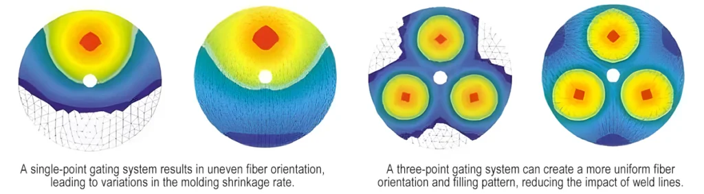
Using a three-point balanced gating system, the plastic melt flows radially from the gates, converging at the flow fronts to form three weld lines. At these weld lines, the orientation of fibers tends to be parallel to the flow front. In gears, this results in fibers being radially distributed at the weld lines, while being randomly distributed in other parts of the gear. This creates areas of low shrinkage along the weld lines. The difference in fiber orientation between the weld lines and the rest of the gear is less pronounced than in gears with a single gate, leading to higher gear precision. Figure 4 shows a schematic comparison of fiber orientation and filling patterns when using a single eccentric gate versus a three-point evenly distributed gate.
Venting Design for Plastic Gear Molds
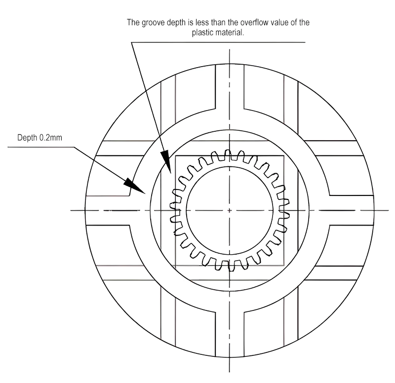
Venting is a crucial aspect to consider in plastic mold design. For plastic gear molds, the design of venting on the tooth surfaces is particularly important. We machine most surfaces of gear molds with a grinding machine. This process ensures a good surface-to-surface fit. However, it tends to result in insufficient filling at the last areas during the injection process. To eliminate trapped air, it is necessary to create venting grooves on the tooth surfaces. Generally, the design of these venting grooves on the tooth surfaces is as shown in Figure 5.
Structural Design of Plastic Gear Molds
Given that plastic gear injection molding often uses point gates, the mold structure commonly adopts a three-plate design. Figure 6 shows the design diagram of a gear mold, and Figure 7 displays the actual gear mold. The working principle of the gear mold is as follows:
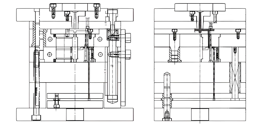
After completing the injection molding action, the movable part of the mold begins to open under the drive of the injection molding machine:
- First Stage of Parting: Due to the action of spring 1, the stripper plate begins to part from Plate A. The sprue puller pin action fixes the main channel on the stripper plate and causes the gate to break away from the product.
- Second Stage of Parting: After the mold opens 95mm, under the action of the tie-bar assembly, the stripper plate begins to separate from the faceplate, releasing the main channel from the sprue bush.
- Third Stage of Parting: As the mold continues to open, under the action of the tie-bar assembly, Plate A begins to part from Plate B. After opening to 90mm, the ejector plate starts to move, ejecting the product. During this process, the guide posts of the ejector plate are used to enhance the balance of ejection. The ejector plate resets under the action of spring 2. This completes the entire mold opening and ejection action.
Manufacturing of Plastic Gear Molds
In the process of molding plastic gears, the gear mold is the key equipment for shaping the plastic gears and ensuring their precision. The plastic gear mold can be divided into two main parts: the gear cavity and the mold frame. The gear cavity, also known as the gear ring, is the most critical and precision-demanding part of the entire gear mold manufacturing process.
1. Gear Cavity Machining
The machining of the gear cavity is key in the manufacturing of plastic gear molds. The molding of plastic gears is a form of ‘replica’ processing. In this process, the cavity’s tooth profile is a deformed template of the gear tooth shape. Therefore, it’s essential to strictly control the dimensional accuracy and surface roughness of the cavity. It is essential to avoid defects such as burrs, eccentricity, and surface scratches. Therefore, a strict gear cavity machining process must be established to ensure the precision of the cavity production.
There are mainly four methods for machining the gear cavity: wire cutting, electrical discharge machining (EDM), electroforming, and beryllium copper alloy casting. Each of these methods has its advantages and disadvantages for machining gear cavities. Manufacturers commonly use wire cutting for involute straight cylindrical gears and generally prefer EDM for helical gears. Additionally, they can machine electrodes used for EDM of gear cavities using wire cutting. For helical gear electrodes with a small helix angle (β≤6°), wire cutting is still applicable.
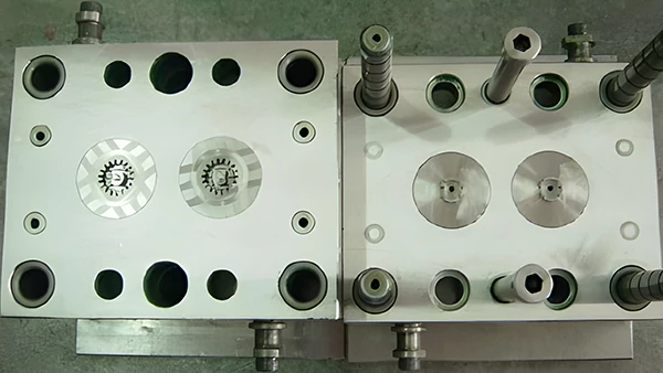
2. Mold Frame Machining
The mold frame, also known as the mold base, is an auxiliary forming part of the gear mold. The process of machining the mold frame is similar to that of common plastic injection molds. Therefore, this article will not elaborate on it. Figure 8 shows the actual image of the gear mold frame machining.