When considering precision machining, mastering advanced techniques is not just a skill—it’s a necessity. One such advanced CNC machining technique that should be considered to cater to certain manufacturing needs is “ramp milling.” Why is this essential? Mainly because it offers a unique blend of efficiency and precision.
This article will unravel all things ramp milling to help you achieve the same efficiency and precision in your production processes. So, without any delay, let’s explore further.
A Brief Overview of Ramp Milling
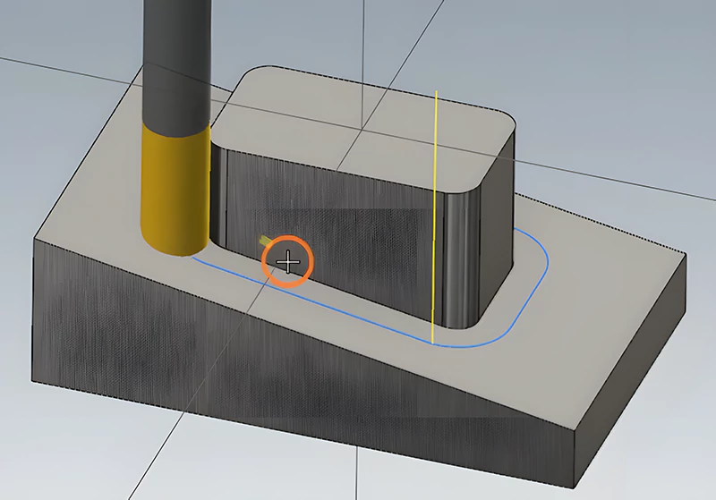
Ramping is a dynamic machining method that entails a cutting tool‘s simultaneous radial and axial motion, forging an angular tool path. The primary purpose is to navigate intricate contours seamlessly, especially when crafting closed forms like pockets, cavities, engravings, and holes.
Unlike traditional methods, ramping eliminates the need for initial plunges with an end mill or drill, streamlining the machining process.
Now, if you are already well-versed in the basics of machining, understanding and mastering ramp milling operations becomes a pivotal skill. Particularly in micromachining, where precision is paramount, ramping proves indispensable.
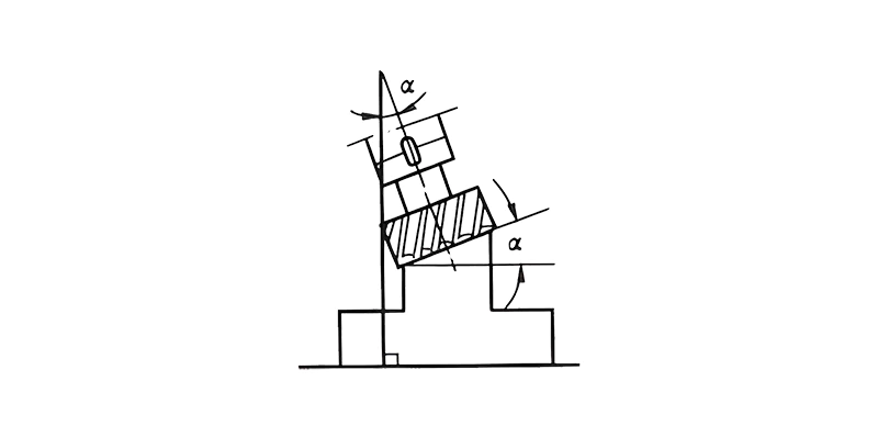
The ability to create closed forms without the drawbacks of plunging ensures a smoother, more efficient workflow. Moreover, ramp milling emerges as a reliable solution in the delicate world of micromachining, where even the slightest imbalance in cutting forces can spell tool failure.
Exploring Ramping Toolpaths: Linear vs. Circular
Linear Ramping
Linear ramping, a widely employed and efficient approach, is a game-changer in machining closed slots, pockets, and cavities. This method, also known as two-axis ramping, eliminates the need for a drill, streamlining the machining process. It involves simultaneous feeding in the axial (Z) and one radial direction (X or Y).
Circular Ramping
Alternatively, Circular ramping, helical interpolation, spiral interpolation, or orbital drilling introduces a spiral motion along a circular path (X and Y), combined with axial feed (Z) at a defined pitch.
This method is always preferred over linear ramping, ensuring a smoother process with reduced radial engagement. The result is pure down-milling and enhanced chip evacuation, particularly when executed with a counterclockwise rotation.

Understanding Starting Ramp Angles
Another key consideration for effective ramp milling processes is starting ramp angles. A recommended range of 3° to 10° ensures optimal results for soft or non-ferrous materials.
Conversely, a narrower range of 1° to 3° is advised when dealing with hard or ferrous materials. These starting ramp angles serve as a guide, allowing manufacturers to navigate the intricacies of ramp milling with precision and confidence.
Successful Ramping Techniques
Now that we understand the key facets of ramp milling operation, let’s explore the tips and considerations for successful ramp milling:
Linear Ramping Tips
- Understanding Simultaneous Cutting: Three critical cutting processes occur simultaneously during linear ramping. These are:
- Periphery cutting with the leading insert.
- Bottom cutting with the leading insert.
- Bottom cutting with the trailing insert.
- Dealing with Cutting Forces: Cutting forces generated during linear ramping are axial and radial, exerting additional stress on the tool, especially during full slotting operations.
- Stress Reduction Recommendations: To mitigate stress and ensure optimal performance, it’s advisable to:
- Reduce the feed to 75% of the normal rate.Implement the use of cutting fluid to facilitate effective chip evacuation.
- Limit linear ramping to narrow slots measuring less than 30 mm wide, especially if access to circular ramping is restricted.
Circular Ramping Considerations:
- Cutter Diameter Selection: Selecting the appropriate cutter diameter ensures alignment with the desired hole size. This ensures that the insert cuts over the center line of the hole, avoiding any misalignment issues.
- Pitch (P) Considerations: The pitch (P) should not exceed the maximum permissible pitch for the chosen cutter concept. This value depends on the hole diameter, cutter diameter, and the ramp angle being utilized.
- Feed Rate Adjustments: The feed rate is contingent on the peripheral feed rate, calculated as Dvf. However, it necessitates adjustments for tool center feed, ensuring that the programmed cutter path aligns with the desired milling outcome.
Tool Path Correction and Optimization
- Progressive Ramping for Enhanced Productivity: Opting for progressive ramping, involving multiple passes, proves beneficial for increasing productivity compared to single-pass ramping strategies.
- Maximizing Ramp Angles with Tool Diameter Considerations: Adjustments for maximum ramping angles should be made, considering factors like the insert radius and tool diameter. This makes sure that the work is accurate and reduces the chance of damaging the tools.
- Circular External Ramping for Improved Efficiency: Employing circular external ramping with increased tool center feed for external milling allows for a smaller radial depth (ae) and higher cutting speed. This contributes to improved efficiency and machining performance.
Can you Do Linear Ramping Into Solid Stock?
Absolutely! Linear ramping into solid stock presents a unique challenge and opportunity in machining. This method, involving a full-width ramping approach, demands careful consideration for optimal cutting speeds and feeds.
The End Mill, engaging with the workpiece at 360 degrees, requires reduced cutting speed to preserve the cutting edges and prevent damage.
Understanding Speeds and Feeds in Ramping
Since ramping differs significantly from regular milling, adjusting cutting speeds and feeds becomes imperative. Hence, you can also consider 50-80% of the normal cutting speed. In this approach, the feed should align with the provided table for ramp chip load adjustment based on the ramping angle.
- 0-2.5 degrees: 100% of normal feed rate
- 2.5-5 degrees: 75% of the normal feed rate
- 5-15 degrees: 50% of the normal feed rate
- 15-30 degrees: 25% of the normal feed rate
- 30-45 degrees: 5% of the normal feed rate
Step-by-Step Ramping Guide: Everything You Need to Know
1. Choose the Right Tool
Selecting a tool tailored to handle cutting forces and facilitate chip evacuation is paramount. Using tools like the Kennametal Mill 1™ shoulder mill or others can help exemplify excellence in ramping and milling within confined spaces.
2. Determine Ramp Angle
The ramp angle choice hinges on tool geometry, material properties, and the intended depth of cut. Seeking advice from a Kennametal expert can provide clarity if uncertainties persist.
3. Program the Tool Path
Efficient milling demands precise tool path programming. Utilize CAD/CAM software or manual programming to ensure the tool enters the workpiece at the correct angle, adhering to the desired path.
4. Test and Optimize
Once programmed, conduct tests to optimize the milling process. Adjust cutting speed, feed rate, and ramp angle to achieve desired outcomes.
5. Monitor the Process
Vigilance during milling is crucial. Keep a close eye on cutting forces, chip evacuation, and surface finish to ensure a smooth and successful operation.
Helical Interpolation vs. Linear Ramping: Are They Different?
Understanding the distinctions between helical interpolation and linear ramping is pivotal in ramping. What are these two terms? Let’s briefly explore below.
Helical Interpolation
- Ideal for tighter pockets.
- The cutter moves continuously, distributing cutting forces across the X, Y, and Z axes.
- Precise machining for holes, threads, and grooves.
Linear Ramping
- Involves tool movement along the X, Y, and Z axes.
- The entry angle dictates the cut direction.
- A usual way to start is by using climb milling, where the cutter turns in the same direction as the table moves.
When is Ramp Milling the Answer?
Once you understand how to conduct ramp milling operations, making the most of this milling technique at the right time is important. After all, this milling approach introduces improved chip clearance during extended linear ramping motions.
But there are some downsides to keep in mind, like potential constraints imposed by pocket geometry restricting the feasibility of long linear ramping moves.
Considering both advantages and disadvantages, you can ideally practice ramp milling operations in the following situations:
- Pocket Constraints Exist: In scenarios where traditional linear milling faces limitations due to pocket geometry, ramp milling offers an alternative that optimizes chip clearance.
- Solid Stock Machining is Crucial: Engaging with solid stock demands a nuanced approach. Ramp milling, with its tailored speeds and feeds, ensures the preservation of cutting edges and prevents damage.
- Efficiency and Precision are Non-Negotiable: Whether achieving intricate designs or maintaining tool longevity, ramp milling is a versatile technique that marries efficiency with precision.
Conclusion
This guide serves as a compass, navigating manufacturers through the intricacies of ramp milling and providing step-by-step insights for both linear and circular ramping methods. From understanding speeds and feed adjustments to choosing the right tools and optimizing tool paths, manufacturers gain a comprehensive understanding of the process.
Still have questions? Prototool stands as your reliable ally. As a professional CNC manufacturing company, Prototool brings expertise and state-of-the-art technology. Should you seek assistance, advice, or cutting-edge solutions for your machining needs, Prototool is poised to be your partner in success.

