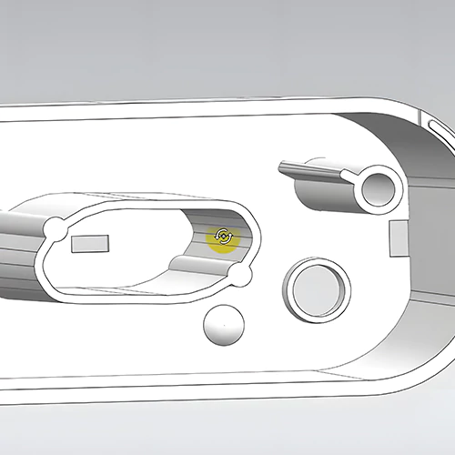
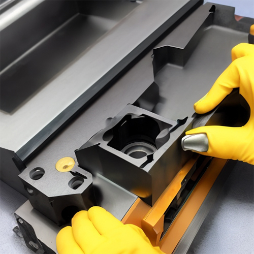
A lifter moves at an angle during ejection to remove steel from undercuts or details inaccessible to slides or other mechanisms. This component has different names and design variations. Lifter design, angle, and materials can all have a significant impact on tool performance over time. Now let’s go ahead and explore all about a CNC tool lifter below in detail.
Suggested: CNC Machine Tools: Choosing the Right Tool for CNC Machining
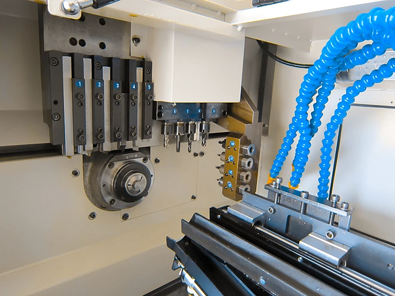
A Detailed Overview of CNC Tool Lifter:
A CNC lifter, also known as a tool lifter or tool changer, is an essential component in CNC (Computer Numerical Control) machines. It is responsible for automatically changing and exchanging cutting tools during machining. The primary purpose of a CNC lifter is to enhance productivity and efficiency by eliminating the need for manual tool changes.
A CNC lifter design typically includes a tool magazine, an arm or carousel mechanism, and a control system. A tool magazine is a storage unit for various cutting tools, such as drills, mills, taps, and reamers. The arm or carousel mechanism is responsible for retrieving and replacing tools from the magazine and transferring them to the machine’s spindle. The control system coordinates the movements of the lifter, ensuring precise tool selection and positioning.
When a CNC machine requires a different tool for a particular machining operation, the lifter springs into action. It moves the arm or carousel to the desired tool position in the magazine, retrieves it, and transports it to the machine’s spindle.
The machine’s control system then securely locks the tool into the spindle, allowing the machining process to continue seamlessly. Once the tool is no longer needed, the lifter removes it from the spindle. It returns it to the appropriate storage position in the magazine.
The advantages of a CNC lifter are numerous. Firstly, it significantly reduces downtime by enabling rapid tool changes without manual intervention. This feature enhances productivity, as the machine can continue running without interruptions.
Secondly, the lifter allows for increased flexibility in machining operations, as different tools can be utilized for various tasks without operator intervention. It also helps streamline machining by minimizing human error and ensuring consistent and accurate tool changes.
Also Read: Benefits and Applications of CNC Machining in the Medical Industry
Properties of a CNC Tool Lifter:
A CNC tool lifter, also known as a tool changer or carousel, is a critical component in CNC machines that enhances efficiency and versatility. Let’s explore the properties of a CNC tool lifter in more detail:
● Tool Capacity:
The tool capacity of a CNC lifter refers to its maximum tool holding capacity in the magazine. This capacity can vary depending on the size and design of the lifter. A higher tool capacity allows more tools to be stored and used during machining. It enables operators to switch between different tools seamlessly, expanding the range of machining operations that can be performed.
● Tool Change Speed:
The tool change speed is when the CNC lifter retrieves a tool from the magazine and brings it to the machine’s spindle. Faster tool change speeds help minimize machine downtime and increase overall productivity. Reduced tool change times mean more time is spent on actual machining, leading to higher throughput and improved efficiency.
● Tool Selection Accuracy:
Accurate tool selection is crucial for achieving precise and consistent results in machining. The CNC lifter must be capable of selecting the desired tool from the magazine and positioning it correctly in the machine’s spindle. This ensures that the appropriate tool is used for each machining operation, minimizing errors and optimizing the quality of the finished product.
● Tool Locking Mechanism:
Once the tool is brought to the spindle, it must be securely locked to ensure stability during machining. The CNC lifter should have a reliable tool-locking mechanism that firmly holds the tool in position. This prevents movement or slippage during operation, allowing for precise and repeatable cuts.
● Tool Change Flexibility:
A versatile CNC tool lifter offers flexibility regarding tool selection and compatibility. It should be capable of accommodating different types and sizes of tools, such as drills, mills, taps, etc. This flexibility allows various machining operations to be performed without limitations, catering to diverse manufacturing needs.
● Robustness and Durability:
The CNC lifter should be designed to withstand the demands of heavy machining operations. It should be robust and durable, capable of enduring continuous tool changes and maintaining reliable performance over an extended period. A sturdy construction ensures longevity and minimizes the risk of downtime due to lifter failures or breakdowns.
● Ease of Maintenance:
Regular maintenance is crucial to keep the CNC lifter in optimal working condition. The lifter should have a design allowing easy access to its components, making maintenance tasks such as tool magazine replenishment, cleaning, and lubrication straightforward and efficient. Well-maintained lifters contribute to longer service life, improved performance, and reduced chances of unexpected malfunctions.
By embodying these properties, a CNC tool lifter provides a seamless tool-changing process, enhances machining flexibility, and contributes to the overall productivity and precision of CNC machines.
Different Types of CNC Tool Lifters:
Their performance could have been much better because of the enormous mold footprints created by conventional lifter cores. Smaller rod angles are required for reactionary forces and bending moments within typical lifter core rods, which might increase mold die height and footprint.
Also Read: CNC Materials Selection in 2022: An Ultimate Guide
A second guide rod parallel to the lifter rod is used in a novel way to create lifter cores. This arrangement avoids the bending moment encountered in traditional single-rod lifter configurations, allowing for a greater lifter angle while decreasing overall die height and mold footprint. Let’s take a closer look at both of these tool lifter systems:
Lifter Systems with a Single Rod
The designer has many lifter system alternatives when creating mold cores for undercuts and side-action molding. The first method involves the use of movable cores and angle pins.
This solution necessitates a significant amount of mold space. It may need to select a lifting core with a smaller plate size at a bigger die height tradeoff. Angles are likewise restricted in conventional lifter cores. If the molded undercut is deep, the mold footprint may need to be expanded to meet the needed side movement of the lifter core, raising the required die height even higher.
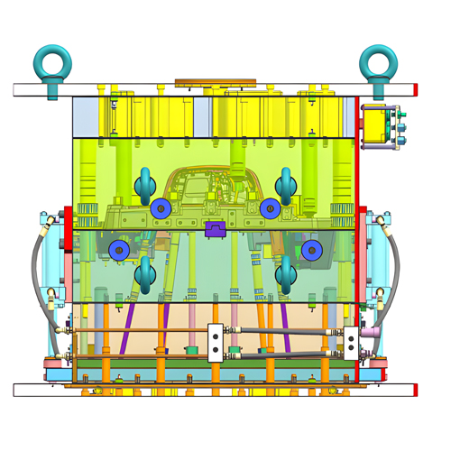
The ejector plate assembly houses the single-rod lifter mechanism’s core, sliding plate, and gib plates. The core plate’s narrow tolerance entrance and exit holes allow close core alignment. This adds to the cost and complicates the processing. The typical configuration has a significant flaw: the bending moment acting on the lifter rod, which causes increased friction, abrasion, and side loads.
Furthermore, premature wear or fracture might occur if the lifter rod needs to be appropriately proportioned. As a result, designers frequently over-design the lifter rod to account for extra loading. This raises component costs and restricts the lifter mechanism’s applicability.
Lifter Systems with Two Rods
Using a second guide rod parallel to the lifter core is a new and underutilized technique. The additional guide rod ensures the sliding base is correctly aligned with the ejector plates. It also reduces bending stresses caused by the average load distribution specified in the conventional arrangement.
The new layout forms a parallelogram between the primary lifter core, secondary alignment rod, plate, and sliding alignment base within the ejector plate assembly. The structurally sound parallelogram eliminates the bending moment that happens in single-rod systems.
A fixed secondary pin eliminates friction between the second pin and the upper alignment plate. The actuation load supplied to the primary lifter core is now centered on the lifter core’s axis and moving in the same direction as the core. Because of the reduced friction and bending moment, the lifter angle can be increased, allowing the designer to lower the required die height and the mold footprint on the platen.
How Are CNC Tool Lifter Angles Determined?
You need to do some simple math to determine the angle at which the lifter must move. All you need to know is how deep the undercut is on the part and how much extraction stroke the tool or machine has (or can have).
For example, if your detail or undercut is 0.5 in. deep, the lifter should move the same distance plus additional space to ensure smooth removal of the part from the mold. How much space is needed depends on the size of the part, the type of plastic used, and how much the plastic shrinks.
Often, the space was part of the design, but because the part shrunk, the lifters were still in place, making it very hard to remove the part. For example, if a PP part was 20 inches long, it could shrink to 0.4 inches.
In the above case of the 0.5-inch undercut, a 0.1-inch clearance would require lifter travel of 0.6 inches. Let’s also say that the ejector stroke is 4 in. This can be summed up as Over 1 inch, 1 degree will move about 0.017 inches. Having said that, 1° will move 0.068 in. over 4 in. So, we need 0.625 inches over 4 inches. To find the angle for our lifter, multiply 0.068 by any number. In this case, we would set the lifter to move 0.612 inches (9° x 0.068).
Final Verdict:
It is easier to ensure correct lifter maintenance if you understand what a CNC tool lifter is, how different designs differ, and how to determine its angles. The greater the angle, the greater the risk of mechanical forces causing wear and failure. Furthermore, the unsupported length is as important as the angle.
Overall, evaluating how much the angle affects your lifter will help you choose a lifter that fulfills your usage requirements while lasting for years. It is easy to prevent lifter difficulties and faults once you understand the many types of tool lifters and which one best suits your machining needs.

