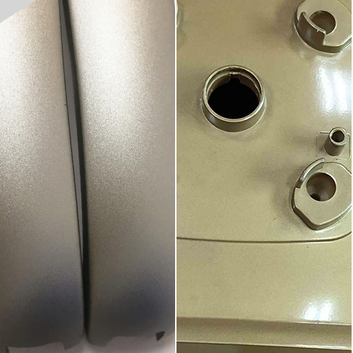
So, what exactly is high speed machining? It achieves a high metal removal rate by combining lighter milling passes with high spindle speeds and feed rates.
High-speed machining reduces cycle time, extends tool life, and boosts shop productivity.
If you’re ready to start a high-speed machining operation in your shop, here are some things to consider.
What is High Speed Machining?
In the 1920s, German inventor Dr. Carl Salmon observed that the maximum amount of heat generated at the interface of the cutting tool and the workpiece occurred at a specified critical spindle speed for a given metal used in the workpiece. This insight led to the development of high-speed machining.
High speed machining is a procedure that focuses on making very quick but also very light, low-pressure cuts; it is used to manufacture molds with complex núcleo e cavidade geometries and structural components in the aerospace sector. The increased material removal rates directly result from the speed with which these cuts are made.
Is it Beneficial?
It certainly is! Indeed, adopting high-speed machining offers a notable advantage: it increases equipment longevity by subjecting both the machine and the cutting tool to significantly less stress. Due to the higher speed and feed rate employed in machining, the material undergoes rapid cutting, resulting in minimal heat transfer during the operation. This reduces shop emissions while simultaneously cutting turnaround time (since less time is required for cooling and hardening).
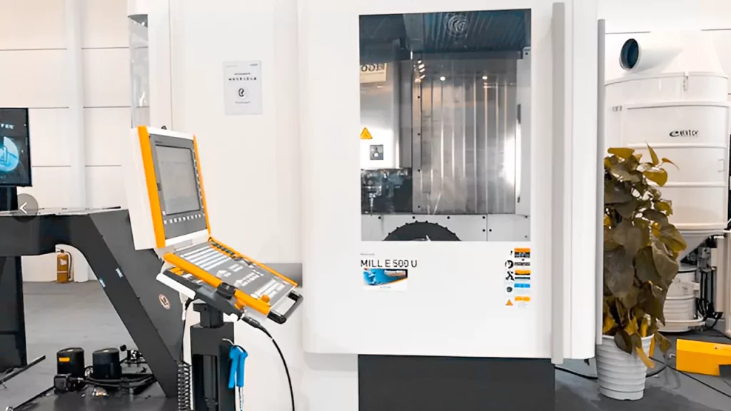
Performing High Speed Machining:
HSM is a collection of techniques in a variety of applications. These technique collections are simple and extremely useful for running any process.
The following are some of the top high speed machining techniques:
1. Milling and Trochoidal Machining
This CNC milling technique can mill deep recesses, tight cavities, and grooves. Trochoidal machining is a good method for slotting unusual and difficult-to-machine materials such as titanium and Inconel.
The following are the major benefits of trochoidal machining:
- Cycle time reduction
- Capable of using multi-fluted tools
- Increased material removal Improved tool life Chip thinning impact
- Limit the number of axial passes.
- Capabilities for high-speed operation
- Maintain constant feed rates.
2. Roughing on the Plunge
This machining is a form of CAM tool path that is manually programmed. It’s like a secret weapon for saving your bacon. The two primary characteristics of plunge roughing are:
- Change the pressures from XY plan to axial Z- up and down forces for more stiff cutting.
- Because of its twisted drills, it can remove more material than an endmill.
Now when deep pockets generate more tool deflection, plunge roughing or milling is ideal. Plunge milling enables you to rough out obsolete machines in the shop.
3. Steps to the Side
This approach helps transition between adjacent tool pathways at high feed rates. It usually results in a sharp stepover maneuver towards the end of the pass. At a high feed, simple round moves can be crisper. Parallel scan line surface machining has been used to finish the manufacture of multi-surface models for the previous decade.
Moreover, a simple looping tool path as sharp alternative twists between scan runs is an effective solution at a reasonable feed rate.
Configuration Tips for CNC High-Speed Machining:
High-speed CNC machining is a significant procedure in Serviços de maquinagem CNC because it can swiftly and correctly machine parts, increasing the corresponding processing efficiency.
There are many distinctions between high-speed CNC and standard machining centers, including spindles, tool magazines, tools, CNC systems, etc. The primary differences are spindle speed and cutting feed. A standard high-speed CNC machining center must meet the standard specifications.
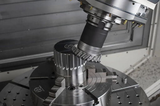
CNC Machining Center with High-Speed Feed Cutting
In CNC machine tools, increasing the cutting feed is comparable to improving the machining efficiency. This is especially true of high-speed CNC machining centers. They typically have a 20-40m/min cutting feed rate. The cutting feed is, of course, the fastest.
The maturation of linear motors has resulted in a qualitative jump in high-speed CNC machining centers, improving machining efficiency and precision in all directions. The linear motor’s driving mode is a non-contact direct driving mode with few moving parts and no distortion issues.
This technique has advanced machine tool manufacture to a level that a standard ball screw cannot match. The linear motor has excellent acceleration and deceleration characteristics; acceleration may reach 2g, 10-20 times faster than the typical driving device, and feed speed is 4-5 times faster.
The Special Spindle supports a High-speed CNC Machining Center
The high speed machining center’s high-speed spindle should have high precision, good rigidity, stable operation, and low thermal deformation. In machining centers, several types of spindles are more common: belt type, gear type, direct-drive type, and electric spindle.
Now direct-drive spindles and electric spindles can be used in high-speed CNC machining centers, but the remaining spindles cannot match the fundamental speed requirements. The spindle speed cannot be less than 10000rpm. Only direct-drive spindles and electric spindles can achieve such a high speed.
Another thing to consider is that a direct-coupled spindle’s maximum speed is lower than that of an electric spindle. Because the cutting force of a direct-coupled spindle is significantly greater than that of an electric spindle, the cutting force of a direct-coupled spindle is far more than that of an electric spindle.
CNC Machining Center Tool with High Speed
The high-speed CNC machining center tool is the tool material of a high-speed CNC machining center, not the type of tool. It centers commonly utilize materials such as polycrystalline diamonds, cubic boron nitride, and hard coating tools. A decent tool can accelerate the cutting speed to the maximum.
In this technology, ensuring dynamic balance in the tool structure becomes crucial, particularly for tools with longer handles. This balance is essential to prevent the high-speed centrifugal force from causing the tool holders or blades with inadequate bending strength and fracture toughness to break. This consideration holds significant importance for high-speed CNC machining centers. Put the operator in danger. The tool holder system selected will also influence the repeatability of the automatic tool change and the tool’s cutting stiffness. Currently, the tool holder system is typically a 7:24 taper single-sided clamping tool holder system.
CNC Machining Center High-Speed CNC System
The CNC system of the high-speed CNC machining center has higher requirements than the ordinary CNC system. The high-speed CNC machining center’s numerical control system must have the fastest data processing capability and the highest functional attributes. This is true for a high-speed CNC machining center with four or five axes.
Moreover, using a numerical control system with a 32-bit or 64-bit processor is preferable. These two numerical control systems are extremely powerful and cannot be compared to conventional numerical control systems.
CNC Programming of High-Speed Machining Center:
Programming a CNC machine for high-speed machining is different than programming a CNC machine for regular machining speeds. Because of the high feed rate and processing speed, high speed machining requires the programmer to anticipate the cutting tool’s path through the workpiece.
Avoiding abrupt changes in the machining direction is just as important as using a small feed and shallow depth of cut during machining when programming NC codes. This is because the cutting speed will drop, and the phenomenon of “crawling” may occur, both of which detract from the quality of the processed surface and can even lead to over-cutting or residue, tool damage, and spindle damage.
Particularly when you deal with three-dimensional contour processing, you should handle the difficult profile or corner section independently of the rest of the contour. Compared to the “Zigzag” method, the straight-line method, and other generic approaches, processing all surfaces simultaneously is preferable.
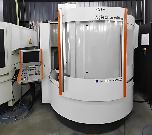
We advise you that the cutting tool enter the workpiece slowly during high-speed machining and that the tool does not re-enter the workpiece after cutting out. Because of this, it is preferable to gradually re-enter a cutting layer after cutting out rather than to enter abruptly. Number two: horde as much as you can. Because variations in load induce tool deflection, which negatively impacts machining accuracy, surface quality, and tool life, it is important to keep your cutting parameters stable by maintaining a constant cutting thickness, feed rate, and cutting linear speed.
Pre-processing some challenging areas of the working contour is often a necessity. This helps prevent the high-speed finishing of small-diameter tools from falling behind the larger-diameter tools used in the preceding process. This results in a dramatic increase in the work required to cut.
Currently, “processing residue analysis” is a feature available in several CAM programs. By utilizing this feature, the CAM system can pinpoint the precise location of the machining residue following each cut. That’s the secret to high speed machining, which relies on a consistent tool load. Additionally, essential is a fruitful actualization.
The shorter the tool path is, the better. Thus, the maximum feed rate may be maintained throughout the machining process, even in the face of dense clusters of data points and abrupt shifts in the cutting direction. To minimize the need for frequent calls and conversions of acceleration/deceleration programs, the “Zigzag” cutting path makes use of an “arc” (or similar arc-shaped line segment) to join two neighboring straight line segments.
Furthermore, the CAM system’s automatic overcut (residual) retention feature in high speed machining is critical for machining accuracy and safety. Because workpiece overcut (residual) damage is irreversible. The tool is also severely damaged, necessitating the creation of an accurate and continuous digital model of the machined geometric surface and an efficient tool path-generating algorithm to assure the integrity of the machining contour. Second, the capacity of the CAM system to check the tool path is critical.
All in all, on the one hand, it enables the programmer to test the program’s accuracy before sending the processing code to the workshop. On the other side, it has the potential to optimize the software. The processing pipeline automatically adjusts the feed rate to ensure it is always at the maximum safe feed rate.
—
For more details and queries related to high speed machining, consult our professional and skilled CNC machining team at Prototool.

