Part craftsmen typically provide mold design job books based on molded part task books. To assure the logic and consistency of the mold manufacturing process, optimize the processing process, and improve fabrico de moldes progress, each mold factory normally develops a process standard fit for its factory, including using unique injection mold parts.
This article will discuss common injection mold parts, their applications, and things to consider when employing them throughout a factory’s machining process.
Types of Injection Mold Parts:
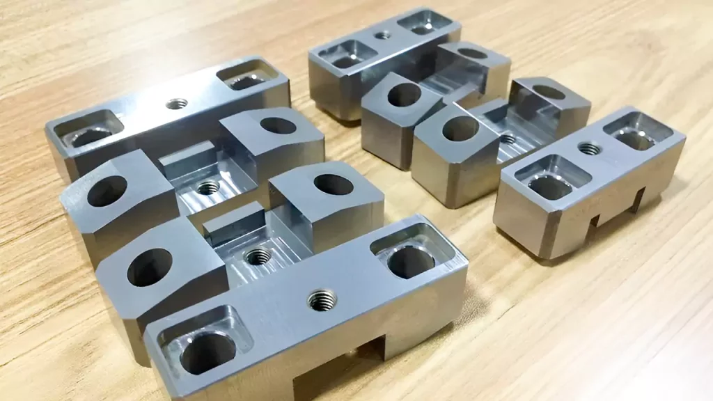
Core:
In injection molding, the núcleo do molde refers to a solid component that is used to create the internal features and cavities of a molded part. It is typically made of hardened steel and is separate from the mold cavity itself. Mold cores are used in conjunction with the mold cavity to form the complete shape of the molded part.
Lifter:
The injection mold lifter is an essential component that makes the whole injection molding process successful. Why is that? Because the lifter is used at the final stage of producing plastics. This is when the molten plastic has been poured into the mold and is ready to be removed.
Additionally, there are so many details regarding the mold. It opens and closes to allow molten plastic in and solidify. Moving forward, when it is ready, products with undercuts are removed from the mold using a lifter.
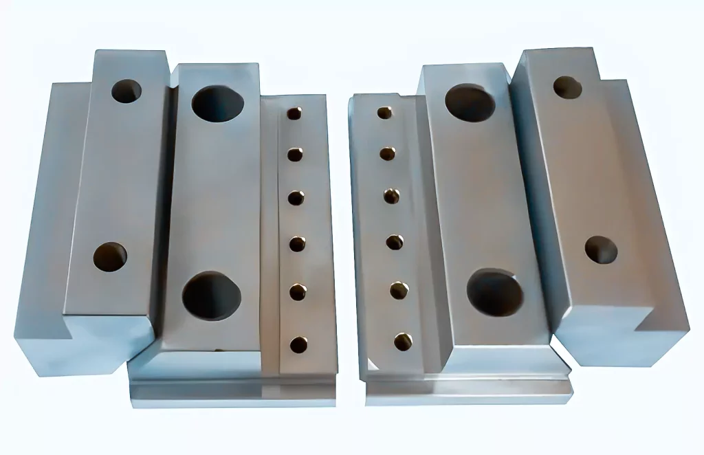
Insert:
Mold inserts are irregular mold accessories implanted in the mold to attach the mold plate. Mold inserts do not comprise a fixed shape and structure, and they must usually be tailored by the actual mold construction, which has high precision requirements.
Furthermore, the mold inserts are suitable for reaction, injection molding, and hot embossing. They can endure temperatures of up to 150° C and pressures of up to 10 MPa with ease.
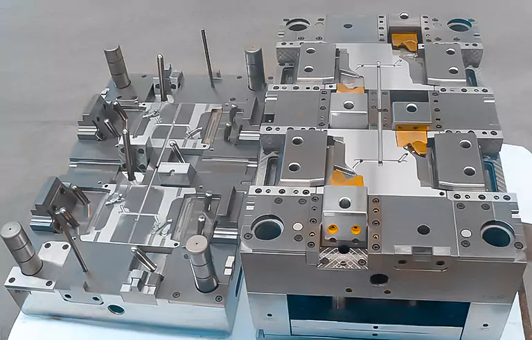
Slide:
However, in most cases, the mold release direction of a specific part may not be consistent with the mold opening direction of the máquina de moldagem por injeção (product undercut). Hence, the slider, also called an injection molding slide, is a molding mechanism developed to solve problems associated with the undercut.
The fundamental idea is to rotate the mold’s normal opening and closing motion horizontally instead of vertically.
Forming surfaces, slider bodies, guide pins, wedges, press blocks, and wear plates are the fundamental components that makeup slide mechanisms. Other common components include a pressing block. The injection mold slider is subject to wear and tear during normal operation.
Additionally, surface nitriding is frequently conducted to mitigate some damage and keep the components in working order for longer. Although designing intricate shapes is the most intriguing aspect of working with a slider, an additional obstacle is preventing displacement that may occur due to the pressure generated throughout the injection molding process.
Things to Know Before Processing Injection Mold Parts:
Understanding the primary parts involved in injection mold machining is crucial. However, once you’re familiar with the different parts and how to use them, you must understand how to process the injection mold parts machining as a craftsman or worker in a factory.
This process involves:
The Artisan is Responsible for Creating the craft card
The process reserve amount, the direction of the processing reserve amount, the roughness requirements, and precautions should all be mentioned in the process card when the craftsman compiles it.
Writing the processing process card principle: Priority is given to using equipment with high processing efficiency to ensure accuracy and quality. This is done to ensure that the cards are written correctly. Milling machines, Máquinas CNC, and grinding machines all have a higher processing efficiency than wire cutting and electric pulse, with milling machines’ processing efficiency being the slowest and grinding machines’ processing efficiency being the fastest.
Considering this, it is impossible to make arbitrary adjustments to the drawing’s dimensions during this process (but only the technician can change it).
The Idea Behind Reserving Processing Capacity
The shape preparation size before heat treatment is unilaterally, plus 0.25mm for workpieces needing heat treatment. Whereas, for grinding machine allowance, mold kernels, and inserts that need CNC rough machining part, the unilateral reserved margin should be 0.2mm. Additionally, the rough milling shape unilateral reserved margin for the fitter machine is 0.3-0.5mm.
Lastly, workpieces that need to be processed by grinding machine after wire cutting require forming injection mold parts unilaterally reserved at 0.05mm, shaping them as rough single-side reserving. A grinding machine must process each workpiece after wire cutting.
Requirements for the Correctness of the Processing
When you’re handling the machining process, you must know that:
- The manufacturing accuracy of the mold size should be within the range of 0.005 to 0.02 mm
- The verticality is required to be within the range of 0.01 to 0.02 mm
- The co-axiality is required to be within the range of 0.01 to 0.03 mm
- Lastly, the parallelism of the upper and lower planes of the moving and fixed mold parting surfaces should be within the range of 0.01 to 0.03 mm.
Now after clamping, there is less space than the overflow value of the molded plastic in the gap between the parting surfaces. At this stage, you should know that:
- The parallelism of the remaining template mating surfaces is required to be in the range of 0.01 to 0.02 mm
- The matching accuracy of the fixed part is generally selected in the range of 0.01 to 0.02 mm
- You should select a bilateral gap of 0.01 to 0.02 mm if the small core has no insertion requirements or has little impact on the size.
- And the matching accuracy of the sliding part is generally selected H7/e6, H7/f7, and H7/g6.
Note: If an insert is on the mirror’s surface, the fit should not be too tight; otherwise, when the insert is knocked back from the front, the tool used to knock will likely damage the mirror. Yet, if this does not affect the size of the product, you can add a gap between the two sides of 0.01 to 0.02 millimeters. Note: The fit should not be too tight if an insert is on the mirror’s surface.
The Basic Idea Behind the CNC Electrode Removal System
The core of the mold cavity should start by removing the major electrode’s look, removing the second main electrode, and ultimately getting rid of the local electrode. After the removal, the fixed mold appearance electrode should consider the overall processing.
Moreover, in the location where the CNC corner is not cleared, you should utilize the wire-cutting angle for clearing the corner. This ensures that the fixed mold appearance surface is uninterrupted and that there are no joints; Stiffeners, ribs, and columns with very little difference in the depth of the moving mold can, to the greatest extent possible, be processed simultaneously on a single electrode.
Furthermore, to avoid carbon deposits caused by electrical impulses, the deeper tendons should be fashioned into inserts, and the electrode should be fashioned independently. Using a CNC milling machine on the moving mold electrode is not recommended after the wire-cutting corner. If this is unavoidable, the electrode should be disassembled before cutting the wire. The distance of more than 35 millimeters between the moving mold’s ribs and ribs or columns ought to be addressed to conserve copper.
The rough spark position of the large electrode ought to be 0.3mm on one side, and the finishing spark position ought to be 0.15mm on one side; the rough spark position of the general electrode ought to be 0.2mm on one side, and the finishing spark position ought to be 0.1mm on one side; the rough spark position of the small electrode ought to be 0.15mm on one side, and the finishing spark position ought to be 0.07mm on one side.
Understanding The Theory Behind CNC Machining
If the product’s appearance allows it, CNC can be finished in place mold cavity core; using the injection mold parts involved in CNC machining. However, you can’t often conduct the process with electrodes during electrical pulse processing. In this scenario, the mold kernel insert needs a CNC thick part, a unilateral reserve margin of 0.2mm, and heat treatment after CNC finishing workpiece.
—–
That’s all to our detailed guide on properly conducting the machining process while using the primary injection mold parts used for mold production processes today.
For more details and queries, feel free to contact us at Prototool.


